Slave to the Game
Online Gaming Community
ALL WORLD WARS
OFFICIAL ILLUSTRATED GUIDE TO MOSCOW ANTI-AIRCRAFT DEFENSE SYSTEM, 1955
S-25 is a surface-to-air guided missile, the first operational SAM system in the Soviet Union. It was deployed in several rings around Moscow, starting in 1955 and became combat ready in June 1956. It was used only to defend Moscow, similar ring was planned to protect Leningrad, but was abandoned due to the appearance of the upgraded and mobile SAM S-75 (SA-2 Guideline). S-25 is short for “System 25”, and was referring to the entire system of missiles, radars, and launchers. Below is the illustration from two unpublished guides for S-25 and V-300 (SA-1 Guild) SAM, compiled in 1955 and classified - until recently.
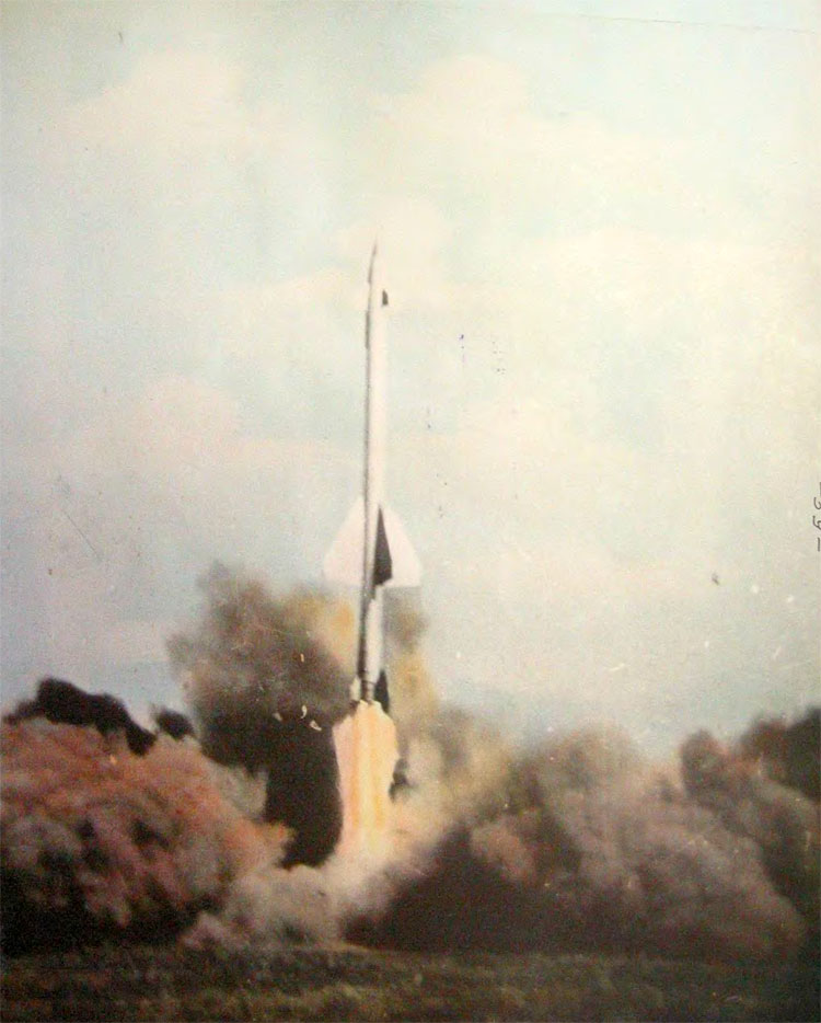
V-300 missile separation from the launch pad
Surface-to-Air Missile V-300 (item 5Ya25), Album of Color Illustrations
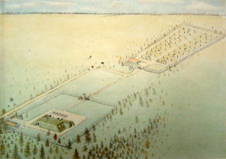
Standard layout of the C-25 SAM site
Missiles launch
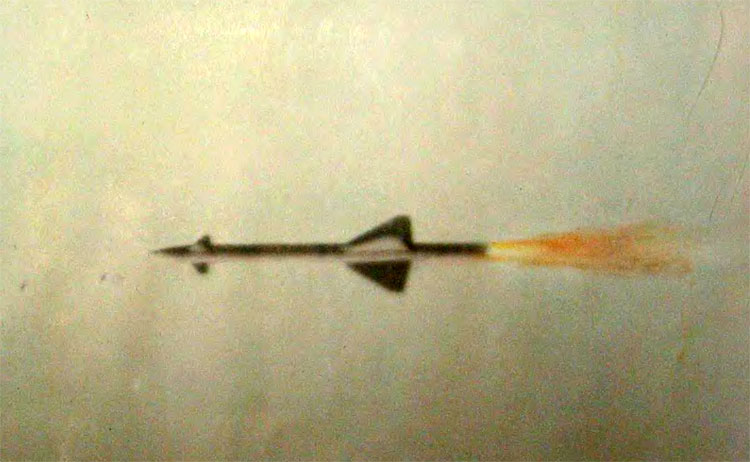
Missile in flight
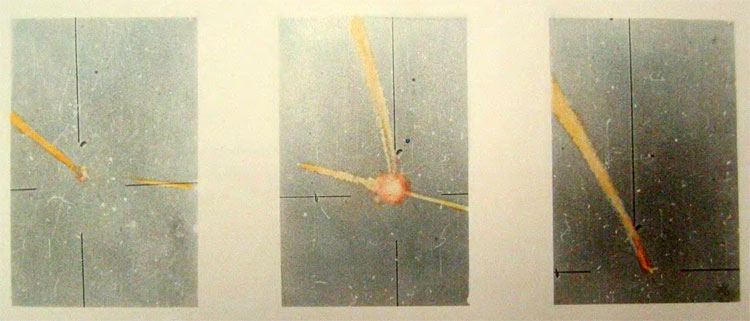
Missile hit on the target aircraft (Tu-16M)
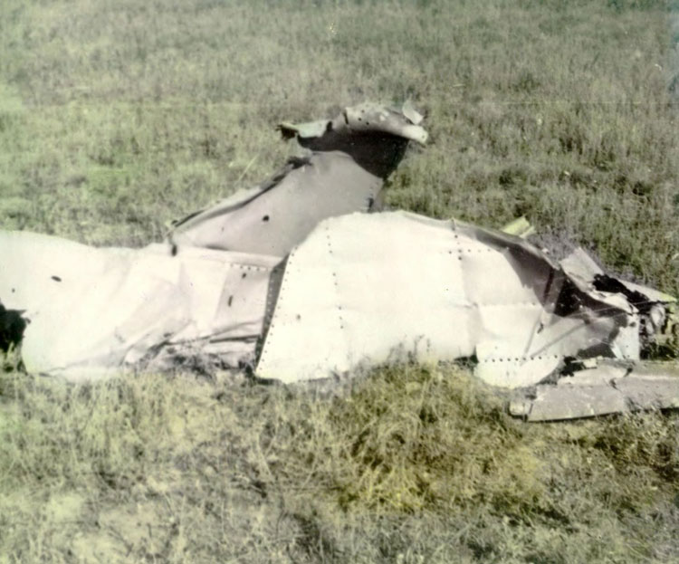
Debris of the target aircraft (1)
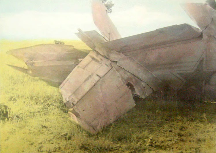
Debris of the target aircraft (2)
B-200 radar station
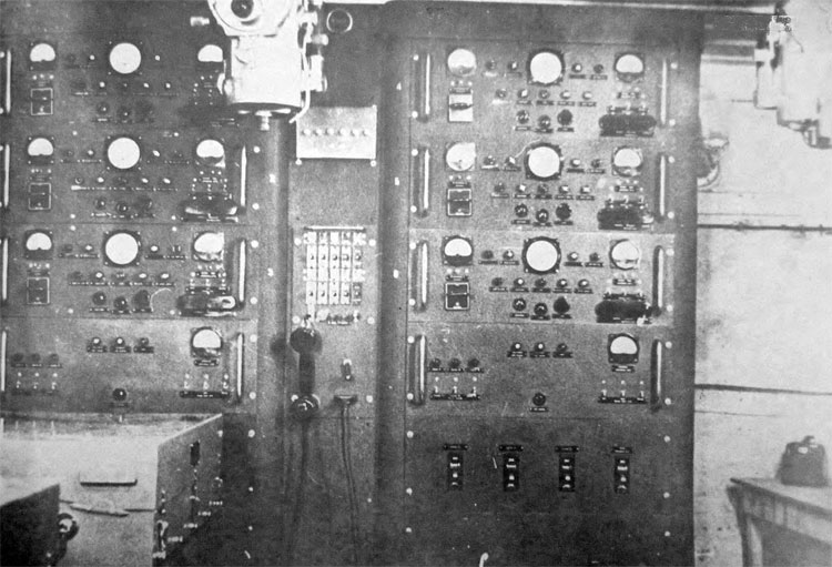
Control room
Switching control stand
Part of the coordinate cabin with panel 3 4M
Guidance control indicator
RS Indicator
V-300 rocket (Click to enlarge)

Rocket Engine 5D25
Autopilot 5A-15
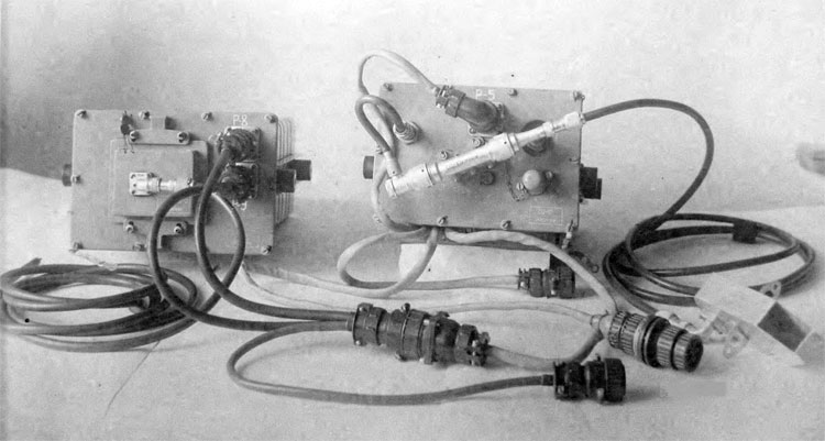
Radio remote control BP-II
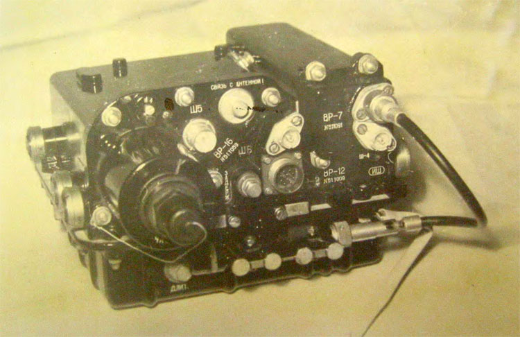
Radio sighting control BP-12
Radio sighting control BP-20
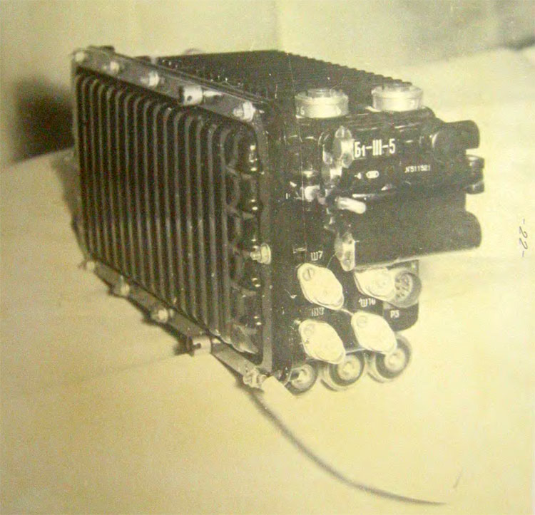
Radio proximity fuse E-802M-II
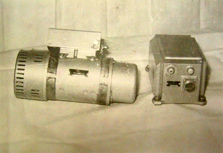
Umformer PT-1200S-4
Self-activating battery P-IM
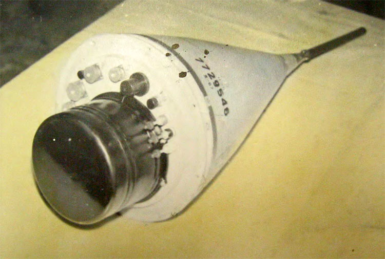
Warhead 5ZH9I
Covering of a target airpalne Mig-15M by V-300 warhead fragmentation field
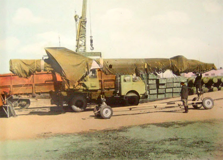
Missile unloading from the railway carriage
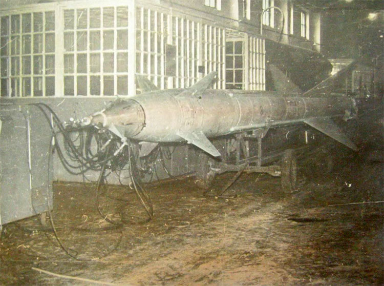
Missile installation on the hangar cart
Missile on the hangar cart
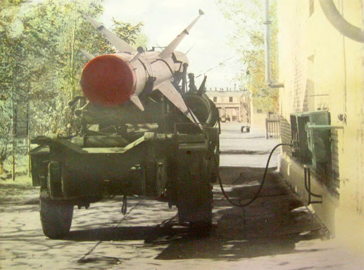
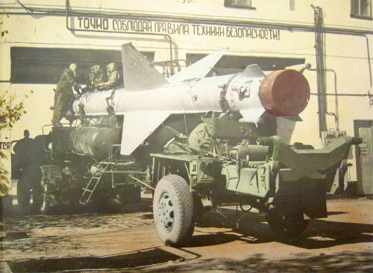
Missile compressed air filling
Missile refueling
Missile refueling by oxidizer
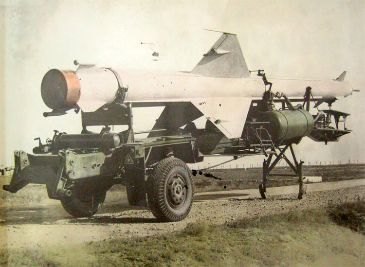
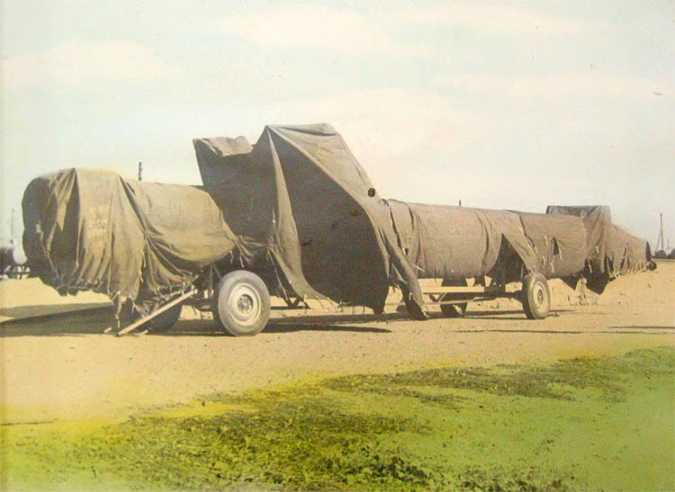
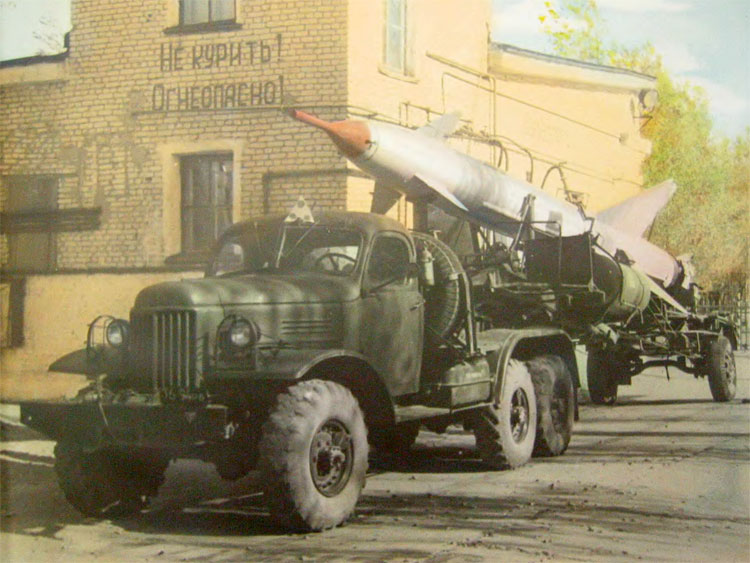
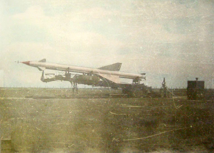
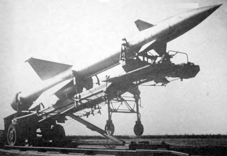
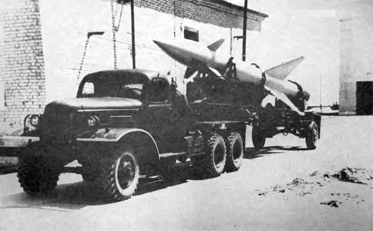
Missile transporting position
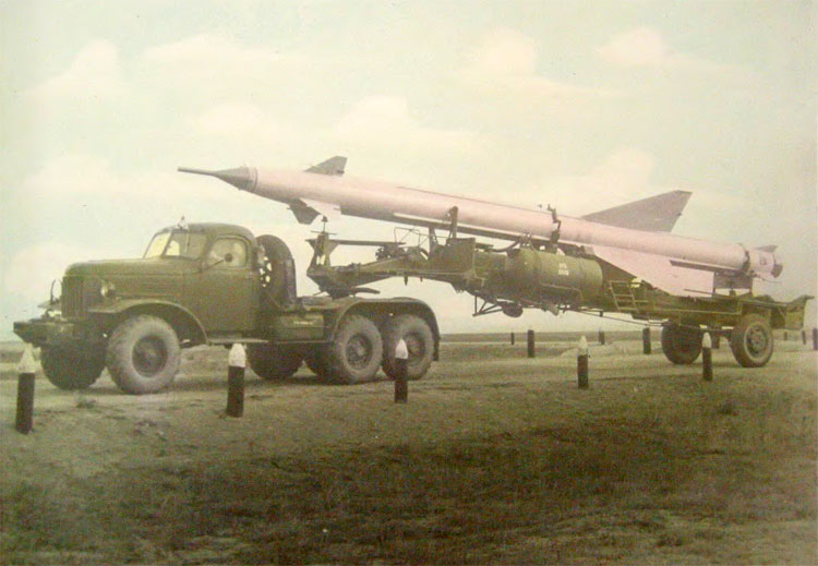
Missile transportation on a semi-trailer
Missile check-out stand
SV-257 autopilot testing equipment
BP-II testing equipment (KIP-PU-I stand)
BP-12 and BP-20 testing equipment (KIP-12U-I stand)
Radio proximity fuse testing equipment (KSE-I stand)
KPSH general testing equipment
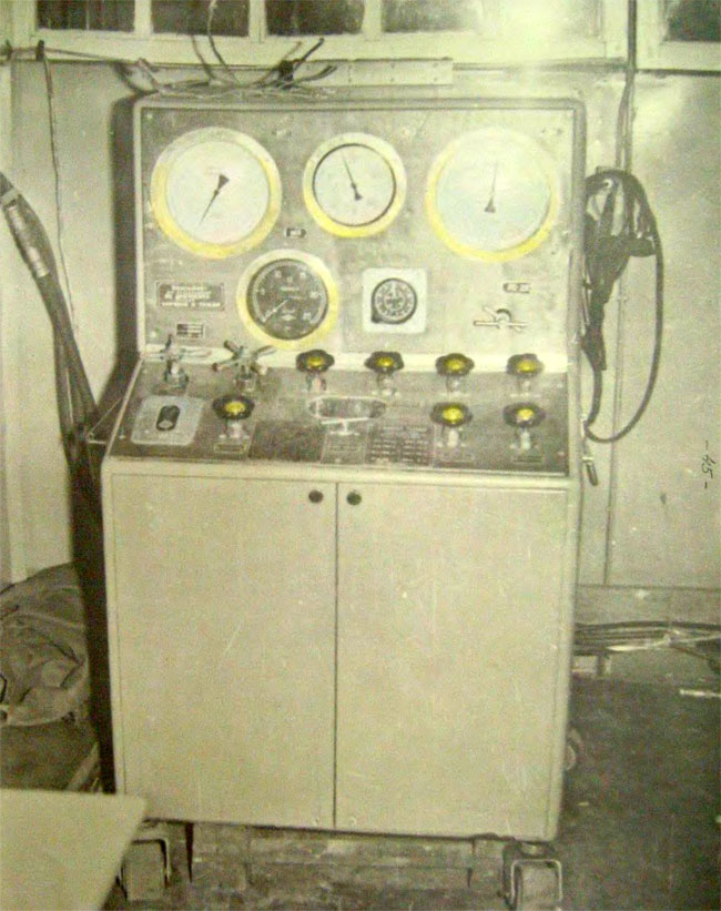
KPS Pneumatic system testing equipment
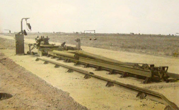
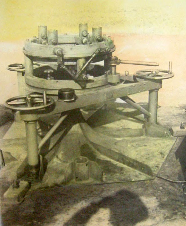
Launch pad equipment with lifting device
Launch pad
Terminal box with detachable plug
Launch pad power cabin (front view)
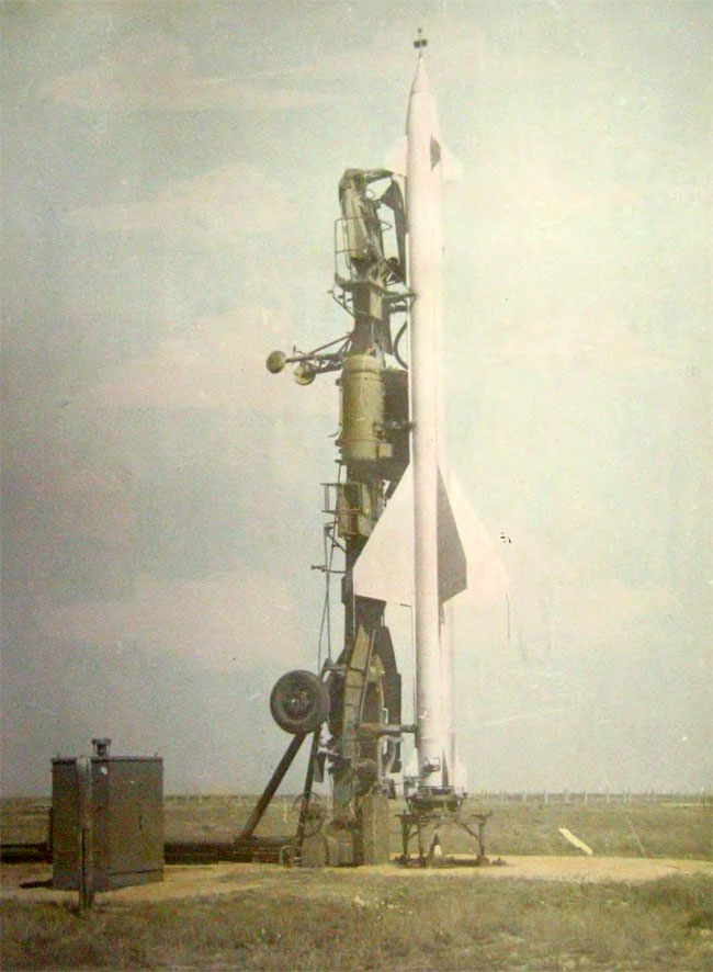
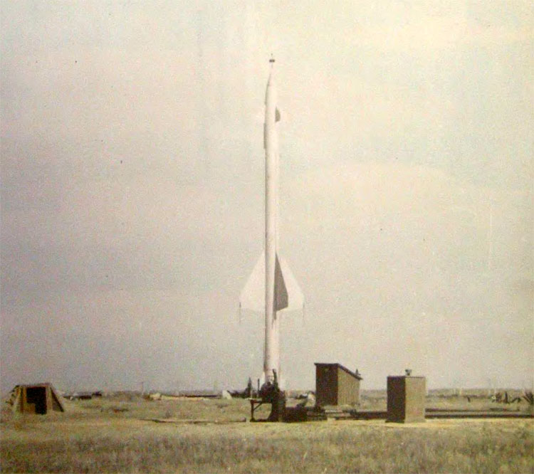
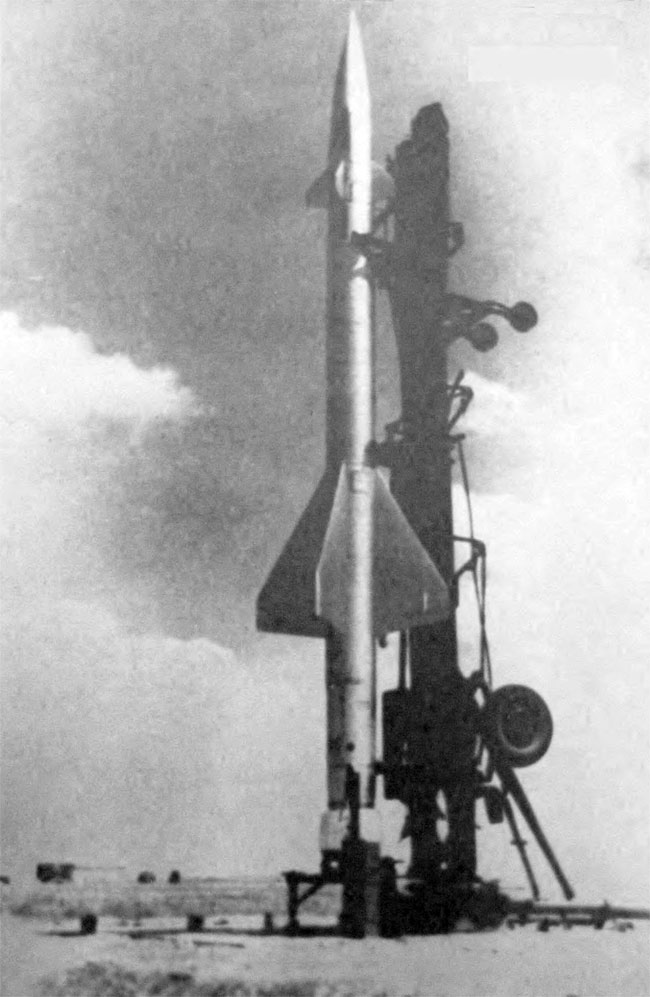
Missile in armed position
Missile on the launch pad
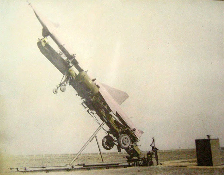
Missile lifting to the launch pad
Missile installation on the launch pad
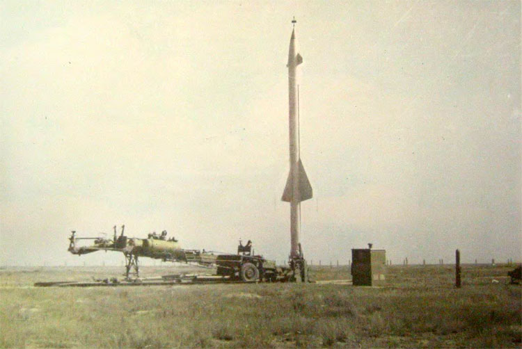
Lowering of the semi-truck
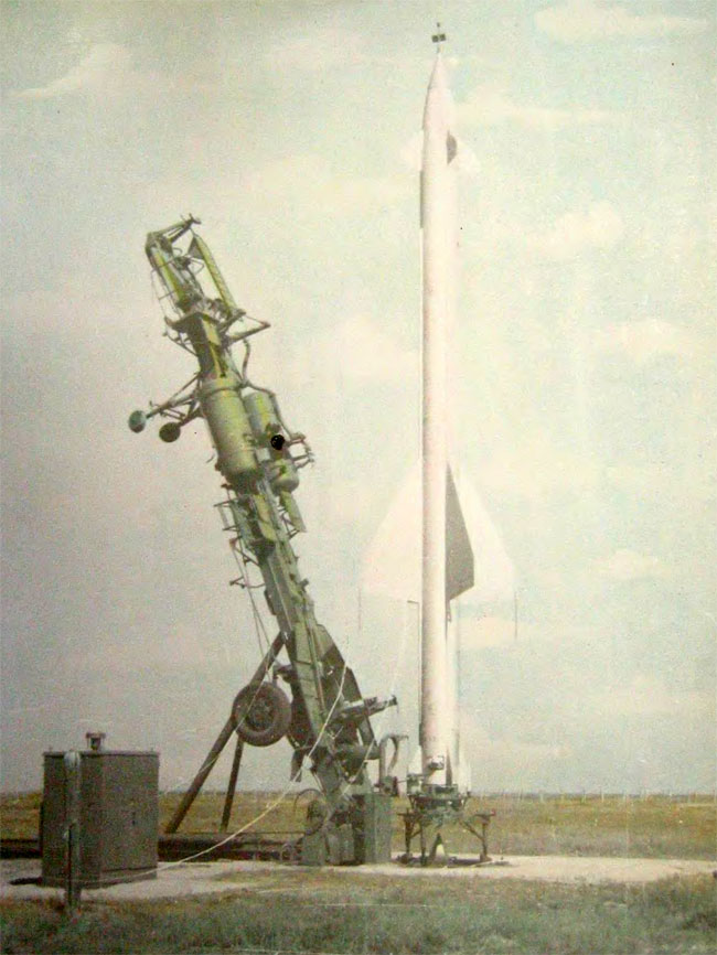
Missile on the launch pad (1)
Missile on the launch pad (2)
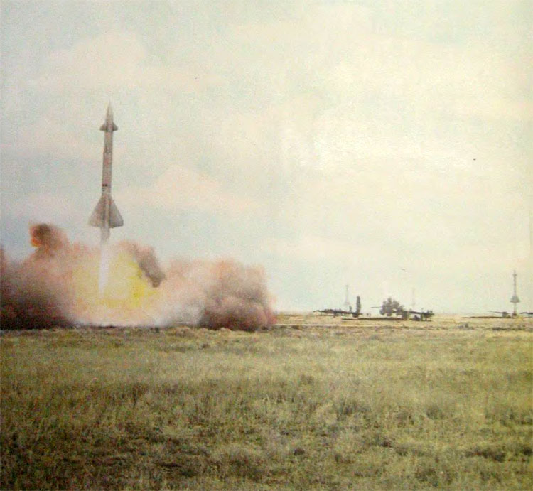
Missile launch
Moscow Anti-Aircraft Defense System
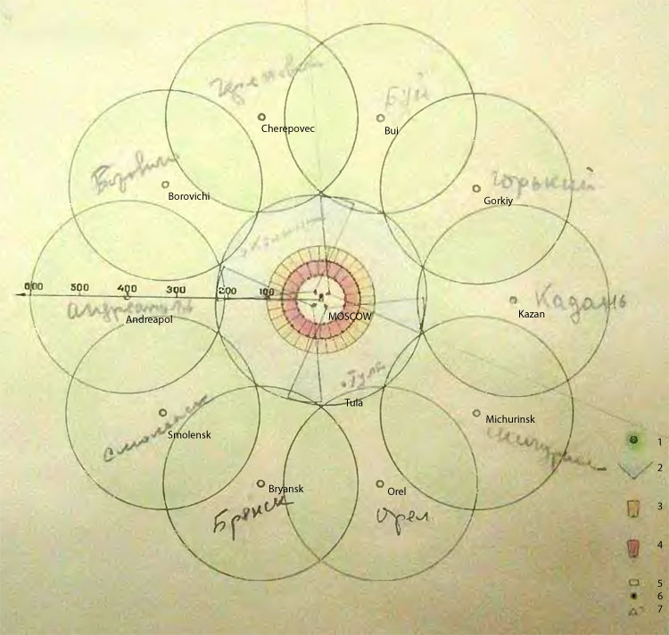
Layout of the Moscow Anti-Aircraft Defense System assets
1. Long-range radar station A100D
2. Short-range radar station A100B
3. Air defense systems of the outer belt defense
4. Air defese systems of the inner belt defense
5. Central command post
6. Alternate command post
7. Secondary command posts
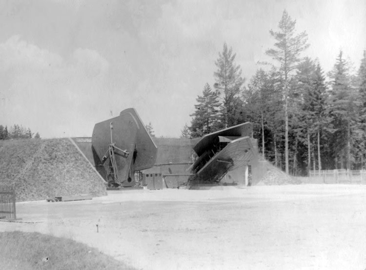
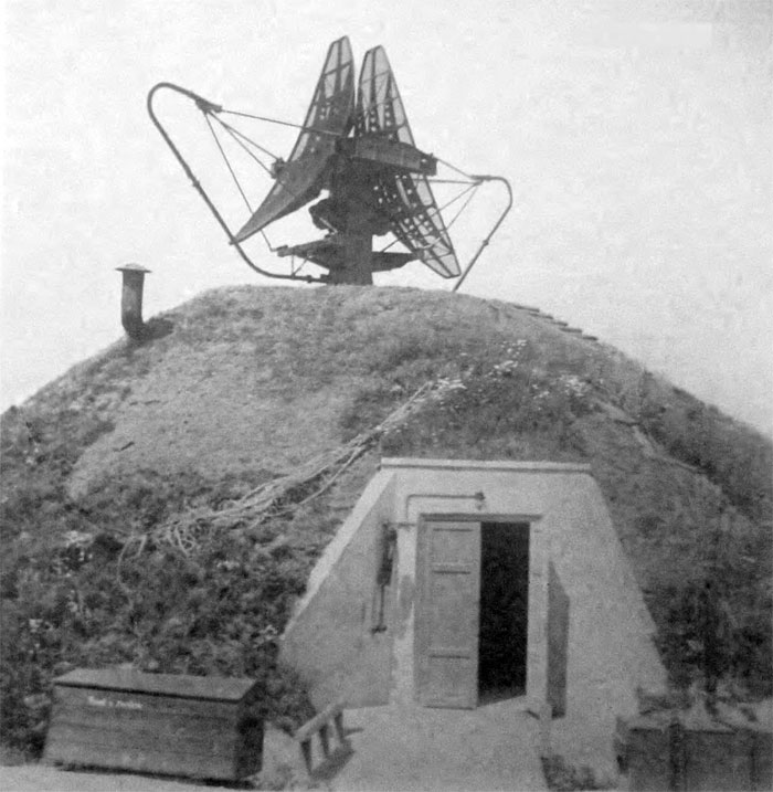
B-200 radar station
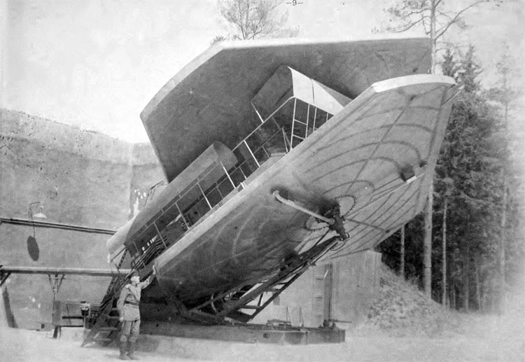
Inclined antenna of the B-200 station - designed for azimuth air surveillance
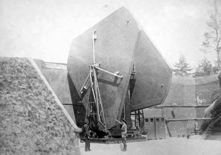
Vertical antenna of the B-200 station - designed for elevation air surveillance
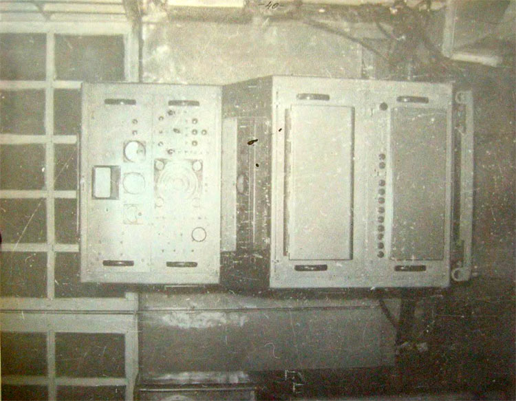
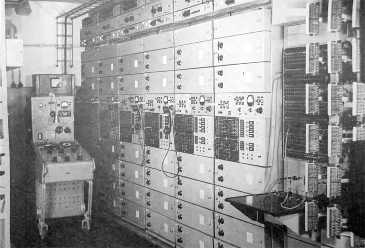
Layout of the radar receiving and transmitting equipment and control stand of the B-200 station in the equipment room
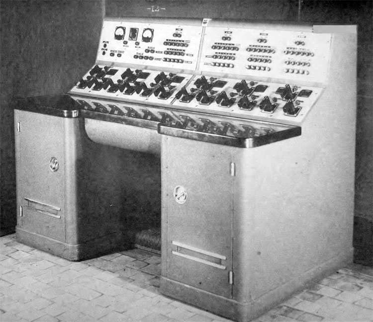
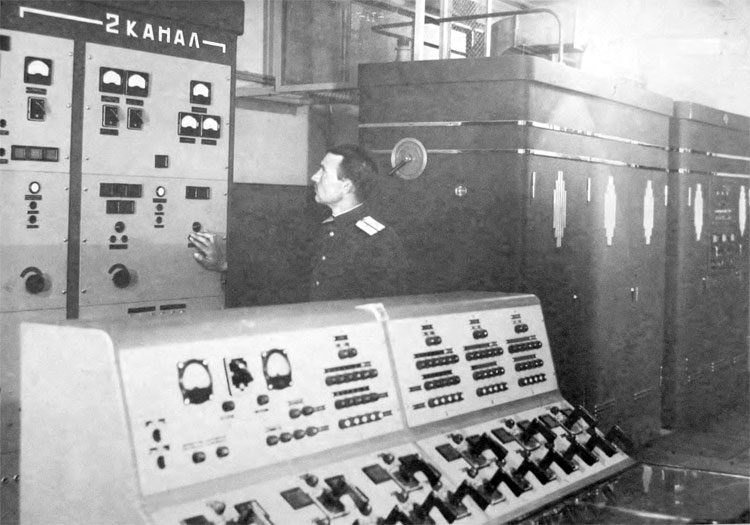
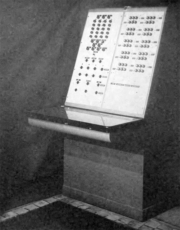
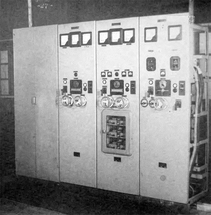
Control stand of the B-200 station - designed for centralized switching on and off of the station
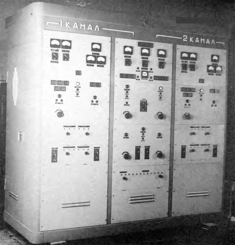
B-200 station transmitters control stand - designed to manage and control station generators
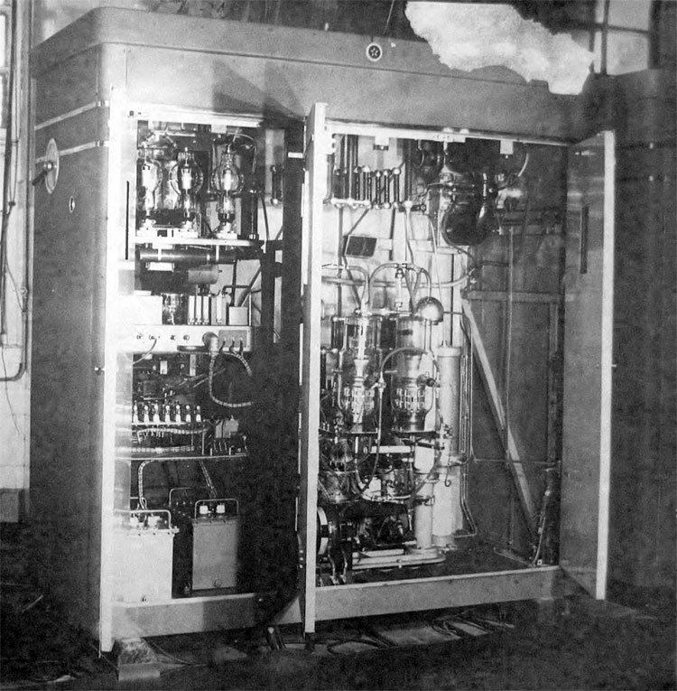
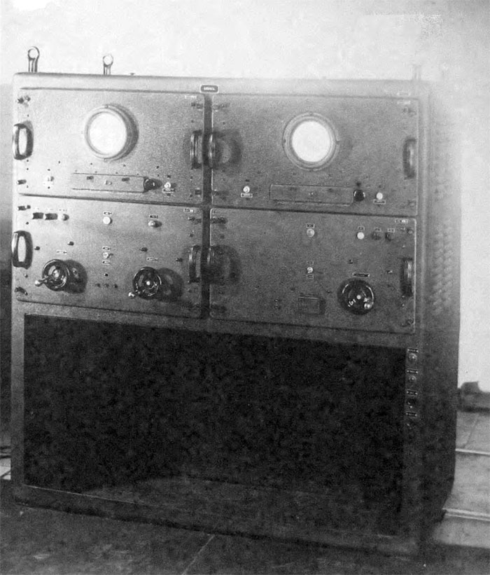
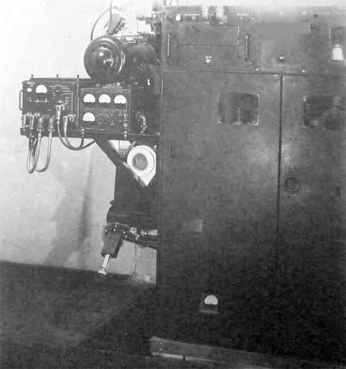
B-200 station generator - designed to produce high-power high-frequency pulses
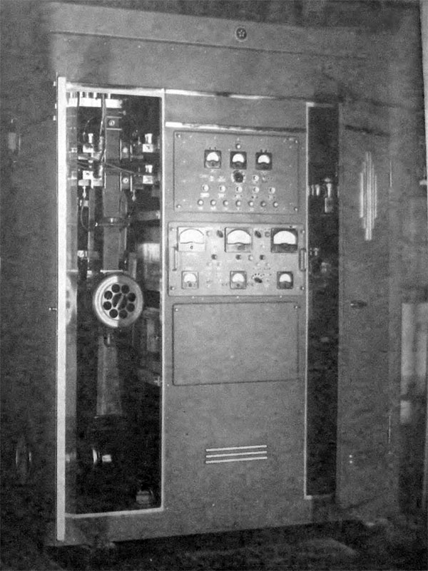
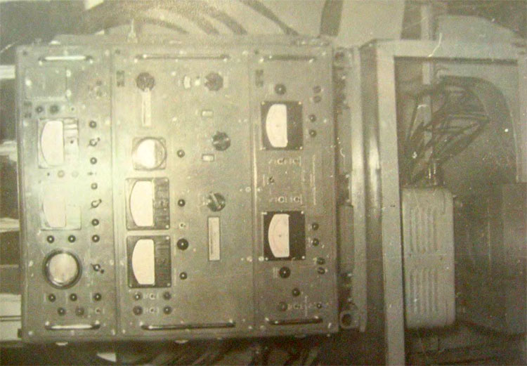
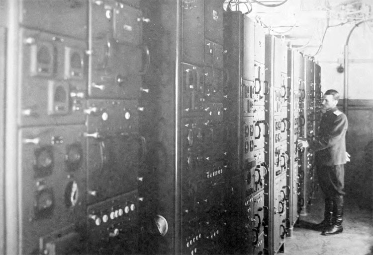
B-200 station input receivers cabin - designed for amplification and conversion of the signals, reflected from targets and emitted by missiles transponder
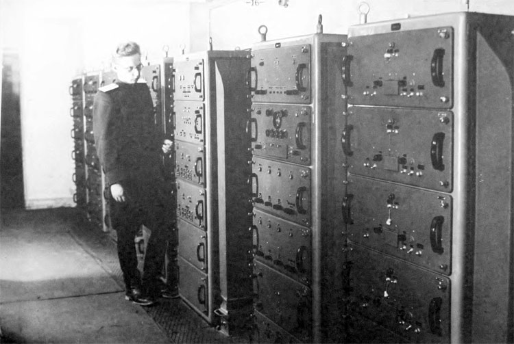
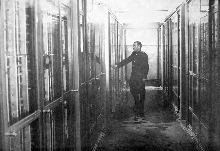
B-200 station layout of the equipment room with main amplifiers of the signals reflected from the targets, main amplifiers of the missiles signal transponders, reference voltage system and indicators marker labels distributors.
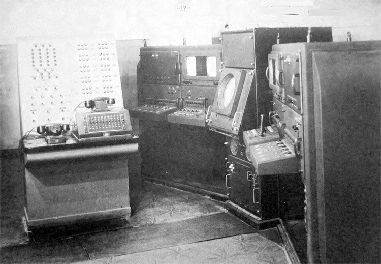
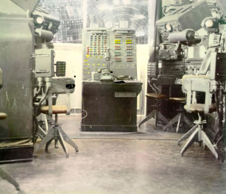
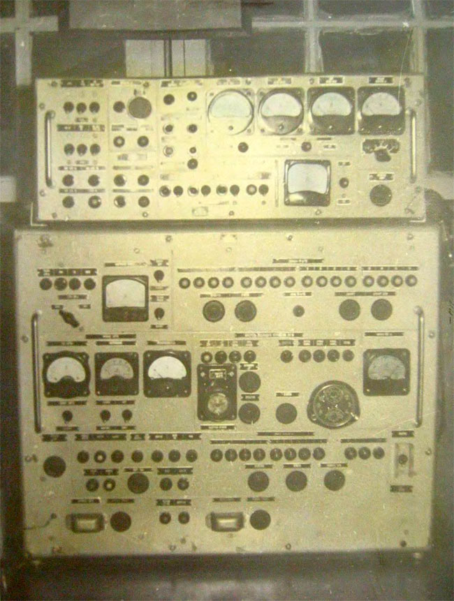
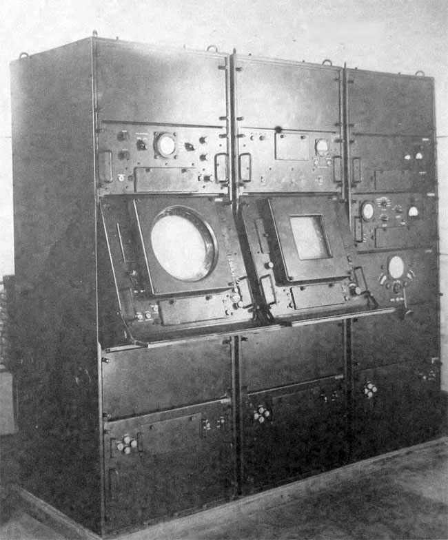
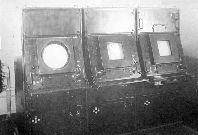
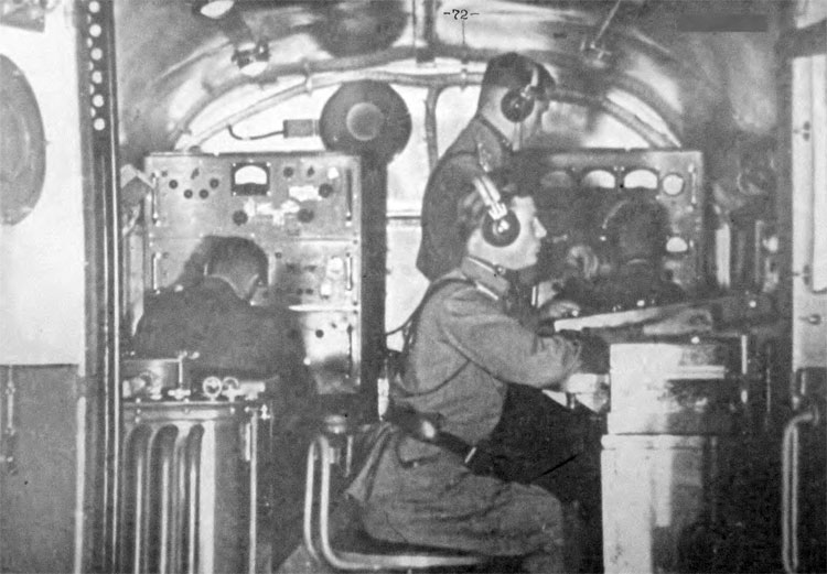
Command and indicators room of the B-200 station. View of the supervisor stand, target designation and guidance cabins, indicator stand I-400 - center and right side of the control room
Command and indicators control room of the B-200 station. View of the manual tracking cabins - right side of the room.
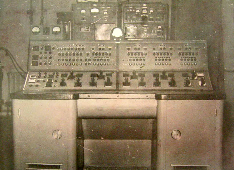
B-200 station supervisor control stand - designed to manage combat work of the B-200 station and firing position.
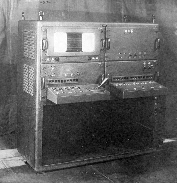
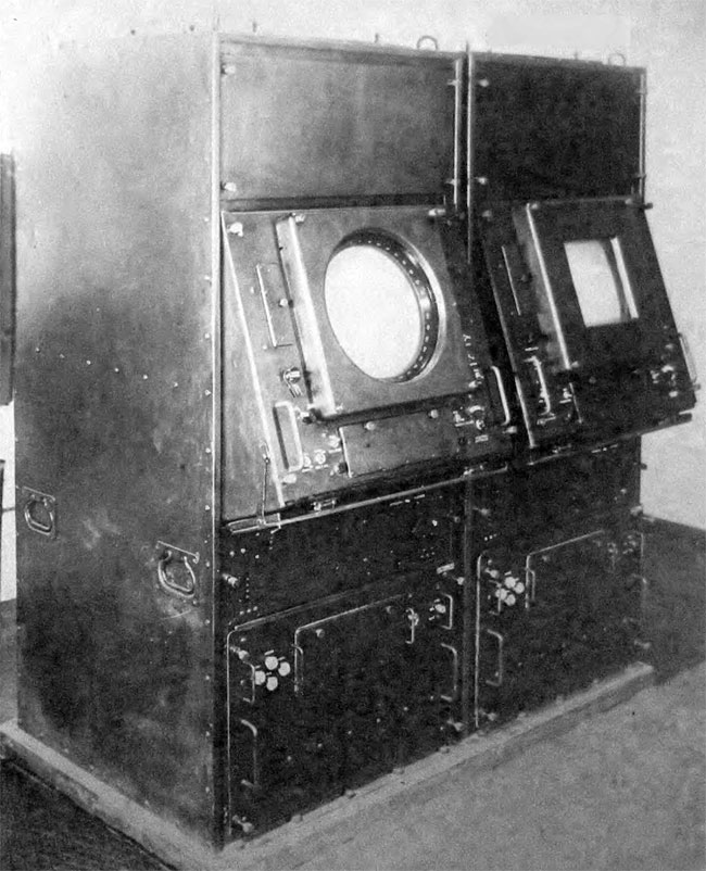
B-200 station targeting and guidance cabin – designed for targets monitoring in the station’s field of vision, targets selection, missiles launch and in-flight monitoring.
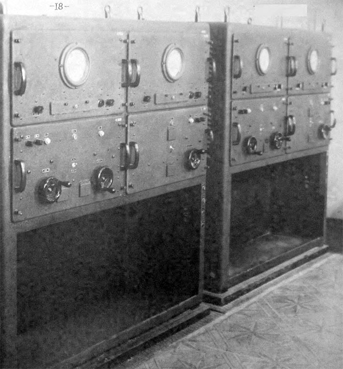
B-200 station cabin of the manual tracking - designed for the manual tracking of a single and multiple targets
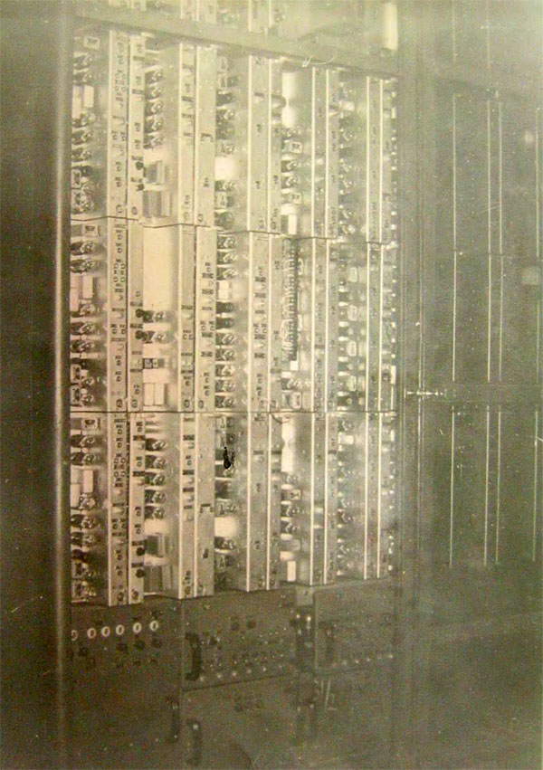
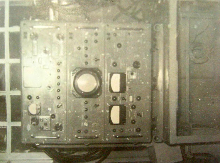
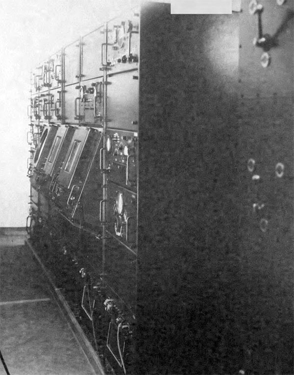
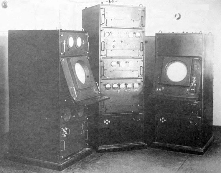
Coordinate-computing equipment layout of the B-200 station equipment room
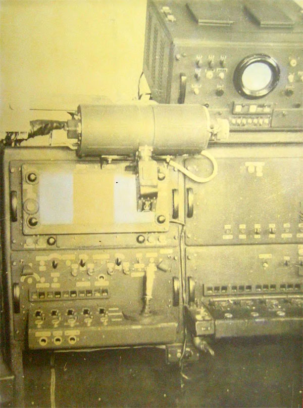
Radio commands transmitter position in the B-200 station equipment room - designed to convert and transmit radio commands to missiles.
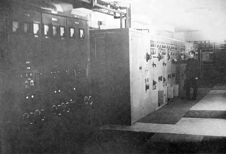
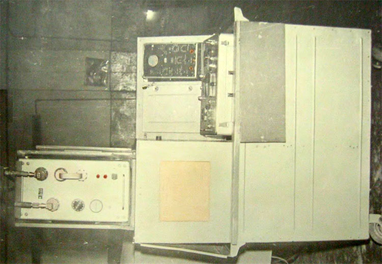
Control equipment layout of the B-200 station power supply
Control stand of the B-200 station antenna electric actuator
Autopilot APV-300c - designed to stabilize and control V-300 missile in flight
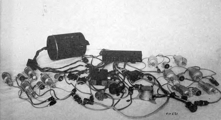
Radio guidance onboard equipment and radio transponder of the V-300 missile
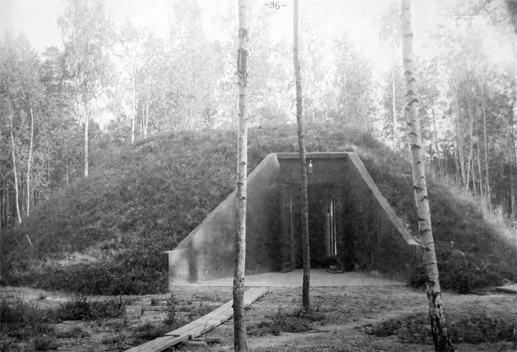
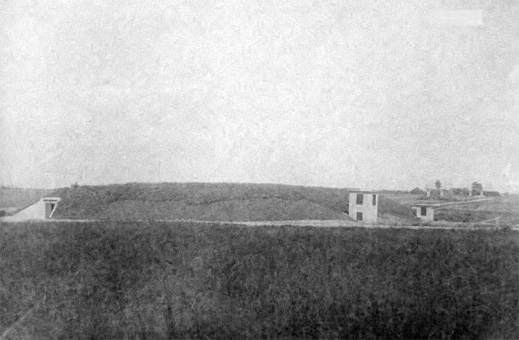
Starting position bunker
Equipment of the starting position bunker (CHP cabin) - designed for preparation and readiness control of the missiles launches
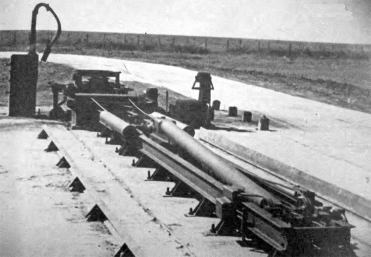
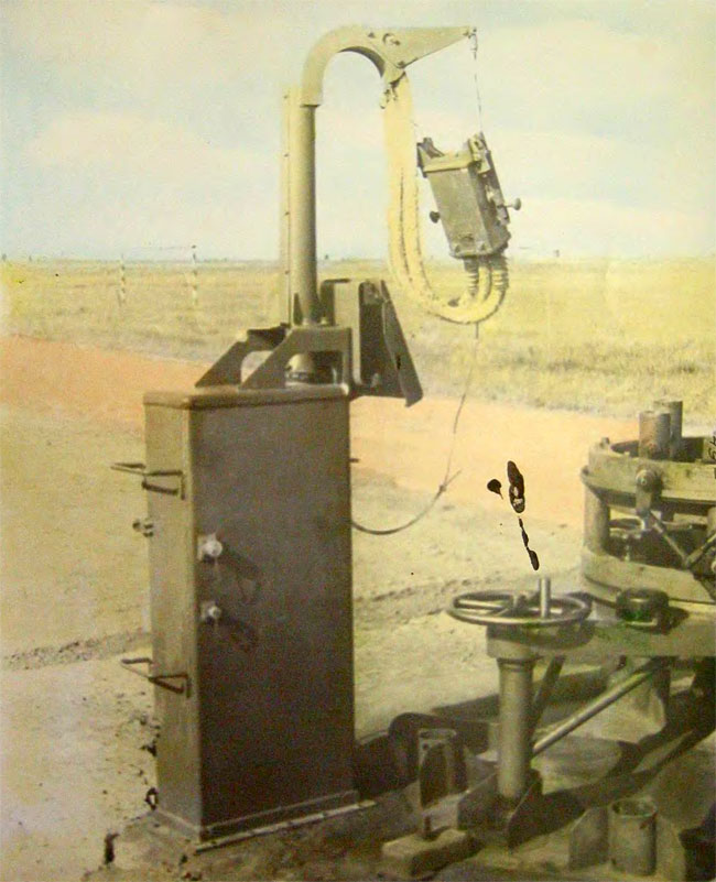
Launch pad equipment – designed for V-300 missile installation in a vertical position and its launch
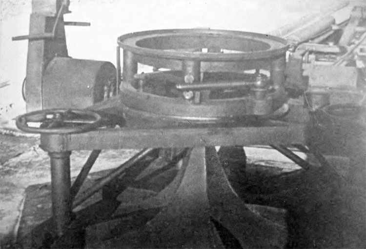
Firing pad of the starting position – designed for missile installation in the vertical position and its launch
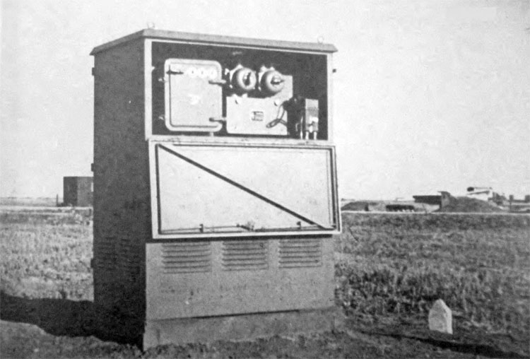
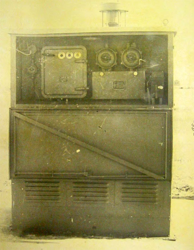
Starting position power cabin - designed to power missile onboard equipment and missile lifting device
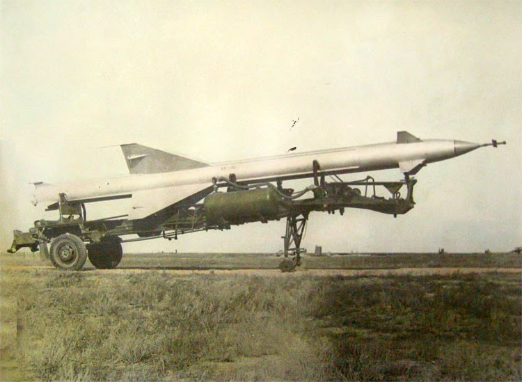
Initial stage of the V-300 missile installation on the launch pad.
Final stage of the missile installation on the launch pad
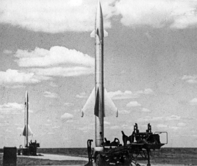
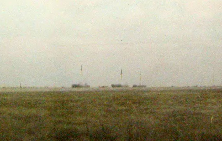
VB-300 missiles installed on the launch pads

V-300 missile launch
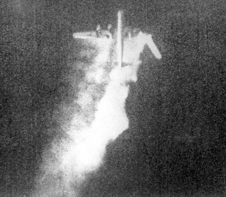
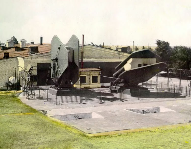
Target airplane [Tu-4 – AWW] after being hit by V-300 missile [Kapustin Jar, April 1953 - AWW]
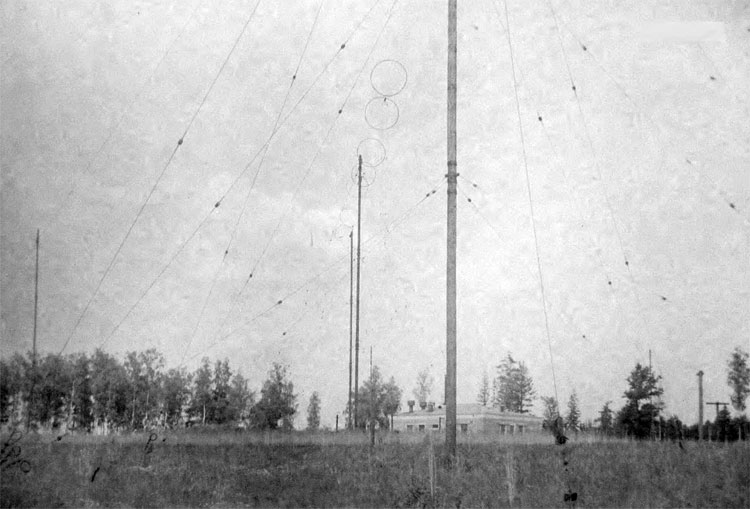
Radar station A-100
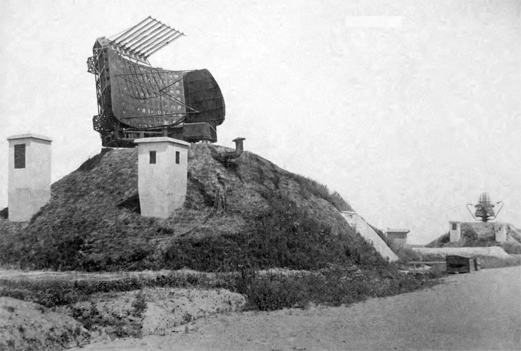
Radar "Kama" of the A-100 station
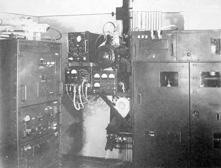
High-frequency equipment of the A-100 station rangefinder
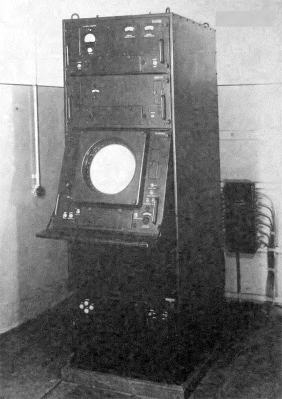
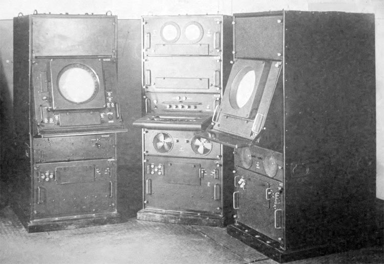
Rangefinder indicator of the A-100 station
Height indicator of the A-100 station - designed for the air targets height and range finding
High-frequency equipment of the station A-100 height finder
Height finder indicator of the A-100 station
Tehnical post of the A-100 station - designed for remote control of the rangefinders and height indicators
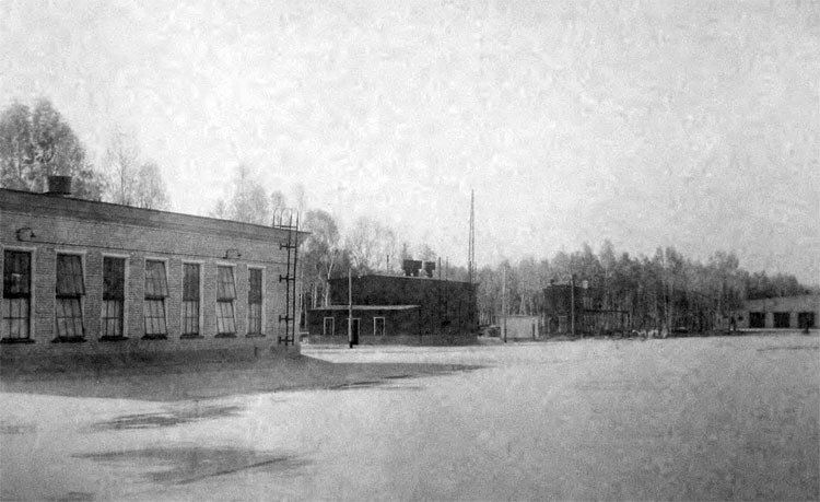
Command post of the A-100 station – designed to transmit data on the air situation to the central command post
Sector post of the A-100 station - designed to transmit data on the air situation to the central command post and guidance station B-200
Television equipment I-400 - designed to transmit data on the air situation from the radar stations "A-100 short-range" to the Central Command post and B-200 guidance station
I-400 indicators of the transmitting television equipment control room (view of the right side)
I-400 indicators transmitting television equipment control room (view on the left side)
Radio transmission center – designed for communication of the central command post with A-100 radar stations
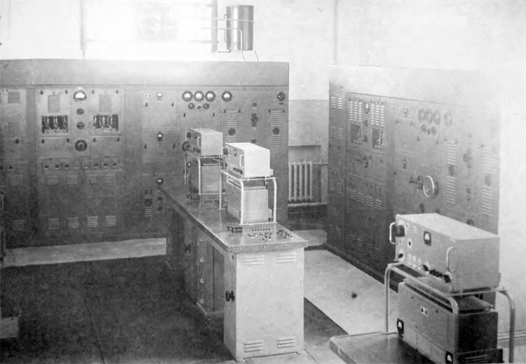
Radio transmitting equipment room of the radio center
Technical position - designed for V-300 missiles pre-launch preparation and testing
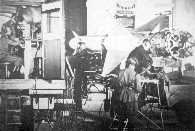
Control and pre-launch verification technical station - designed for check-out of the serviceability of the onboard V-300 missile equipment
Mobile test control unit KUV-300 test equipment layout
Filling V-300 missile with the compressed air from a stationary compressor unit