Slave to the Game
Online Gaming Community
ALL WORLD WARS
GERMAN VOLKSWAGEN 1944 TECHNICAL MANUAL
WAR DEPARTMENT Washington 25, D. C, 6 June 1944
TM E9-803, German Volkswagen, is published for the information and guidance of all concerned.
BY ORDER OF THE SECRETARY OF WAR: G. C. MARSHALL, Chief of Staff.
OFFICIAL: J. A. ULIO, Major General, The Adjutant General.
PART ONE—INTRODUCTION
1. SCOPE.
a. These instructions are published for the information and
guidance of the personnel to whom this equipment is assigned. They
contain information on the operation and maintenance of the German
Volkswagen as well as descriptions of the major units and their functions in relation to the other components of the vehicle.
b. This manual has the following arrangement.
(1) Part One, Introduction, contains description and data.
(2) Part Two, Operating Instructions, contains instructions for the operation of the vehicle, with description and location of the controls and instruments.
(3) Part Three, Maintenance Instructions, contains information
needed for the performance of the scheduled lubrication and preventive maintenance services, and instructions for maintenance opera¬tions which can ordinarily be performed by using organizations (first
and second echelons).
c. The operations described in this manual are based on the
availability of necessary parts, accessories, and tools. Conditions will
arise in which the items referred to in the manual are not available
since they cannot be requisitioned through usual channels. In these
cases, individual initiative must be resorted to when repairs are required.
2. RECORDS.
a. Forms and records which may be provided for use in performing prescribed operations are listed below with brief explanations of each. In case of Volkswagen, use of these forms will be governed by tactical situation and extent to which vehicle is employed.
(1) STANDARD FORM NO. 26, DRIVER'S REPORT—ACCIDENT, MOTOR TRANSPORTATION. One copy of this form should be kept with the vehicle at all times. In case of an accident resulting in injury or property damage, it should be filled out by the driver on the spot, or as promptly as practical thereafter.
(2) WAR DEPARTMENT FORM NO. 48, DRIVER'S TRIP TICKET AND PREVENTIVE MAINTENANCE SERVICE RECORD. This form, properly executed, is furnished to the driver when his vehicle is dispatched on non-tactical missions. The driver and the official user of the vehicle complete, in detail, appropriate parts of this form. These forms need not be issued for vehicles in convoy or on tactical missions. The reverse side of this form contains the driver's daily and weekly preventive maintenance service reminder schedule.
(3) W.D., A.G.O. FORM NO. 6, DUTY ROSTER. This form,
slightly modified, is used for scheduling and maintaining a record of
vehicle maintenance operations. It may be used for lubrication
records.
(4) W.D., A.G.O. FORM NO. 461, PREVENTIVE MAINTENANCE
SERVICE AND TECHNICAL INSPECTION WORK SHEET FOR WHEELED
AND HALF-TRACK VEHICLES. This form is used for all 1,000-mile
(monthly) and 6,000-mile (semiannual) maintenance services and
all technical inspections performed on wheeled or half-track vehicles.
Section II. DESCRIPTION AND DATA
3. DESCRIPTION.
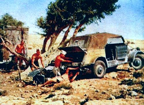
a. General. The Volkswagen is a four-wheeled, rubber-tired,
rear axle drive personnel carrier and reconnaissance car, comparable
in purpose and size to the American 1/4-ton 4x4 truck. No propeller
shaft, as such, is used; the engine, transmission, and differential comprise a unit structure which is secured to the floor at the extreme rear
end of the vehicle. Access to the engine is provided by a hinged door at
the rear of the body. The vehicle has no frame. Instead, a base stamping comprising the floor of the vehicle is ribbed and provided with a
central tunnel to give desired stiffness, to form the foundation of the
vehicle. The main fuel tank is located under the front body panel on
the right-hand side of the vehicle. The spare tire is carried on top of
the front body panel.
b. Engine. The engine is an air-cooled, four-cylinder, four-cycle,
horizontally-opposed type. Intake and exhaust valves are located in
the cylinder head and are operated by conventional rocker arms and
push rods.
c. Transmission. The transmission is the selective, sliding-gear
type. Four speeds forward and one reverse are available". Differing
from American vehicles, no direct drive is used. The fourth speed
forward is an overdrive, having a ratio of 0.80 to 1. A detailed description of the transmission is contained in section XX.
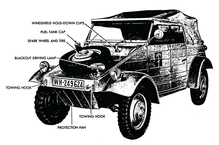
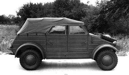
Figure I—Volkswagen—Left Front View
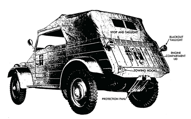
Figure 2—Volkswagen—Left Rear View
d. Differential. A positive locking differential is used in place
of spider gears. Whenever excessive friction is built up, the differential
locks, thereby transmitting torque equally to the two driving wheels.
A detailed description of the differential is contained in section XX.
e. Suspension. All wheels are independently sprung. The two front wheels are sprung on pairs of torsion rods mounted transversely
on the vehicle, with the wheel kingpins being supported on a parallelogram linkage. The two rear wheels are stabilized laterally from the differential housing, and oscillate vertically about centers of the universal joints which are attached to the sides of the differential housing. Suspension of the rear wheels is by torsion arms attached to each end of a torsion rod mounted transversely on the vehicle.
f. Steering Gear. Steering wheel and steering mechanism are of the conventional type commonly used in American vehicles.
g. Braking System. Service brakes operate on all four wheels.
These are mechanical brakes, actuated by cables attached to the foot
brake pedal. The parking brake, through the same system of cables,
also operates the service brakes on all four wheels.
4. TABULATED DATA.
a. Vehicle Specifications
| Vehicle SpecificationsVehicle specifications Vehicle specifications | Metric | US | |
| Wheel base | 2,400 mm | 7 ft 10-1/2 in | |
| Length, overall | 3,740 mm | 12 ft 3-1/4 in | |
| Width, overall | 1,600 mm | 5 ft 5 in | |
| Height, top down | 1,111 mm | 3 ft 8 in | |
| Tire size | 5.25-16 | ||
| Tire air pressure (front) | 1.4 atm | 20.5 lb | |
| Tire air pressure (rear) | 1.8 atm | 26.5 | |
| Tread (front) | 1,356 mm | 53.39 in | |
| Tread (rear) | 1,360 mm | 53.54 in | |
| Crew | 4 | ||
| Weight (empty) | 725 kg | 1.598 lb | |
| Weight (loaded) | 1,160 kg | 2,557 lb | |
| Net load | 450 kg | 992 lb | |
| Ground clearence | 290 mm | 11.4 in | |
| Foot brake works on | 4 wheels | ||
| Hand brakes work on | 4 wheels | ||
| Wheels | Disk | ||
| Type of rims | Drop center | ||
| Front wheel toe-in | 3-6 mm | 1/8-1/4 in | |
| Camber | 2-1/2 deg | ||
| Caster | 5 deg | ||
b. Performance.
| Performance | Metric | US |
| Minimum speed | 3 kmph | 1.8 mph |
| Maximum speed | 8o kmph | 49.7 mph |
| Climbing ability in loose sand | 40 pct | |
| Climbing ability on the road | 45 pct | |
| Fording depth (without wetting engine) | 450 mm | 17.7 in |
| Opearting radius | 400-450 km | 250-280 miles |
c. Capacities.
| Capacities | Metric | US |
| Main gas tank | 30 liters | 7.925 gal |
| Normal fuel consumption | 8 l per 100 km | 30 mpg |
| Transmission and differential | 40 pct | |
| for lubrication change | 2.5 litres | 2.6 qt |
| For filling after overhaul | 3.0 litres | 3.1 qt |
| Engine | ||
| - For oil change | 2.5 litres | 2.6 qt |
| - For filling after overhaul | 3.0 litres | 3.1 qt |
| Steering mechanism | 0.25 litres | 1/2 pt |
5. CONVERSION TABLE.
- Metric to U. S.
1 millimeter equals 0.0394 inches
1 liter equals 0.264 gallons
1 pound equals 0.454 kilograms
1 mile equals 1.609 kilometers
- U. S. to Metric
1 inch equals 25.4 millimeters
1 gallon equals 3.785 liters
1 kilogram equals 2.205 pounds
1 kilometer equals 0.621 miles
Section III. TOOLS. PARTS. AND ACCESSORIES
6. TOOLS.
a. All maintenance operations listed in this manual can be performed with standard tools available to the first and second echelon maintenance organizations. Open-end and socket wrenches used must be in %4-inch sizes to properly fit the metric scale of bolt and nut sizes.
7. PARTS AND ACCESSORIES.
a. Since this materiel is of German manufacture, replacement of various units with corresponding units of American manufacture is limited to minor parts which can be adapted for use on this vehicle by improvising mounting facilities. Examples of such replacement units headlights, coil, wiring, and some of the instruments in the instrument panel. Otherwise, parts replacement will have to be handled by cannibalization.
b. Many vehicles will be found from which the tools and equip¬ment have been removed, lost, or damaged. These may be replaced by cannibalization or by requisition of comparable American equipment through usual channels. Below is a suggested list of American equip¬ment which will be found valuable and useful for proper operation and maintenance of the vehicle. This list is for information only and is not to be used as a basis for requisition.
Tools and Equipment / Federal Stock No.
Ax, chopping, single-bit / 41-A-1277
Extinguisher, fire / 58-E-202
Gage, tire pressure / 8-G-615
Gun, lubr., hand-type / 41-G-1330-60
Oiler, straight spout, 1/2-pt / 13-O-1530
Pliers, combination, slip joint, 6-in / 41-P-1650
Pump, tire, w/chuck / 8-P-5000
Screwdriver, common, 6-in / 41-S-1104
Shovel, D-handle, rd. pt / 41-S-3170
Wrench, adjustable, automobile type, 11-in / 41-W-448
Wrench, adjustable, crescent type, 8-in / 41-W-486
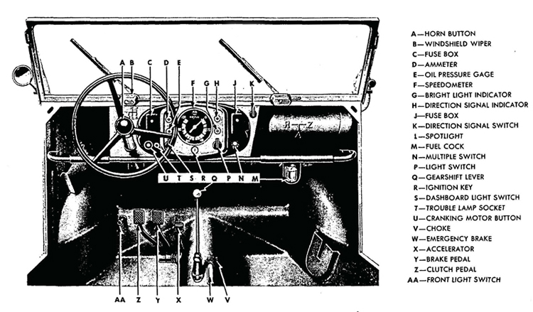
Figure 3—Instrument Panel, Brake, and Shift Levers
PART TWO—OPERATING INSTRUCTIONS
Section IV. CONTROLS AND INSTRUMENTS
8. CONTROLS.
a. Ignition Switch. The ignition switch is located at the lower
center of the instrument panel. A key is furnished to operate the switch.
When the key is inserted and turned, the switch serves to close electrical circuits between the battery and ignition coil, direction indicator light, oil pressure light, and dash light switch. All the other circuits
are opened and closed by their respective switches.
b. Horn Button. The horn button is located in the hub of the steering wheel. When the button is depressed, it closes the circuit between the source of electrical power and the horn, and thus actuates the horn.
c. Cranking Motor Button. The cranking motor button is located
on the extreme lower left side of the instrument panel. When the
cranking motor button is depressed, it closes the electrical circuit between the cranking motor and battery. The cranking motor rotates
and, through a series of gears, rotates the engine crankshaft.
d. Fuse Boxes. Two rectangular fuse boxes, one at each end,
are located on the instrument panel. Most of the electrical circuits in
the vehicle pass through one, or the other, of these boxes. In the event
a circuit is shorted or overloaded, the fuse burns out. This opens the
circuit and prevents damage to any item of equipment, or injury to
personnel.
e. Trouble Lamp Socket. This socket provides an electrical
outlet in which a corded lamp may be plugged, thus providing portable
illumination. The socket is located just to the right of the cranking
motor button.
f. Dash Light Switch. The dash light switch is located on
the instrument panel to the right of the trouble lamp socket. When
turned on, it closes the circuit between the source of electrical power
and the dash light, thus turning on the dash light.
g. Light Switch. The light switch is located on the instrument
panel just beneath the bright light indicator. When the light switch is
turned on it operates the service headlights and service tail and stop
light.
h. Multiple Switch. The multiple switch is located just to the right of the light switch. The multiple switch has three positions: one "OFF"; one to turn on the blackout driving light and the blackout tail and stop light; and one to close the circuit to the headlight switch.
i. Direction Signal Switch. The direction signal switch is located at the extreme right-hand top side of the instrument panel. It controls the two direction signals located on the outer ends of the windshield. When the switch is turned to the left, the left direction signal is extended, and when the switch is turned to the right, the right direc¬tion signal is extended. "OFF" position of the switch is vertical.
j. Fuel Cock. The fuel cock is located at the fuel strainer beneath the fuel tank. Closing the cock shuts off the flow of fuel from the fuel tank to the carburetor on the engine.
k. Foot Dimmer Switch. The foot dimmer switch, located on the upward slope of the floor and convenient to the driver's left foot, is used to control the output of the front headlights. Stepping down on the switch operates it.
1. Clutch Pedal. The clutch pedal, mounted on a horizontal shaft extending outward from the tunnel in the center of the vehicle, extends upward to a position convenient to the driver's left foot. Depressing the pedal serves to disengage the clutch and thus interrupt the flow of power from the engine to the transmission and driving rear axles. The clutch pedal must be depressed in order to shift gears.
m. Brake Pedal. The brake pedal, located just to the right of the clutch pedal, is connected to the mechanical brakes on each wheel through a system of cables. Depressing the brake pedal pulls the cables, which in turn expands the brake shoes within the wheel drums, and slows, or stops the vehicle, depending on the amount of pressure exerted.
n. Accelerator. The accelerator is located just to the right of the brake pedal. In its released position, the accelerator is adjusted so that the engine will run at idling speed. Depressing the accelerator increases the speed of the engine.
o. Choke. The choke is mounted to the right of the gearshift lever on the tunnel extending through the center of the vehicle. Pulling out the choke enriches the mixture of gasoline and air being fed from the carburetor into the engine, and thus aids in starting a cold engine.
p. Gearshift Lever. The gearshift lever, convenient to the driver's right hand, is mounted on the tunnel extending through the center of the vehicle. The lever may be shifted into any of six positions. Five of these are power positions, and one position is neutral. The purpose of the gearshift lever is to provide a means of selecting the proper transmission gear ratio to suit driving conditions.
q. Parking Brake. In its release position the parking brake lever rests in a horizontal position on the tunnel extending through the center of the vehicle. Pulling up on the parking brake lever operates the same cables as are operated by the service foot brakes, and thus slows or stops the vehicle, depending on the pressure exerted on the brake lever. A toothed segment, on which the lower end of the parking brake is mounted engages a latch on the side of the parking brake lever, providing a means of locking the lever at any position along its arc of travel. This latch is released from the segment by depressing a button in the top of the parking brake lever.
9. INSTRUMENTS.
a. Oil Pressure Gage. The oil pressure gage is the lower warning light on the left-hand side of the instrument panel. The light glows
green when the ignition is switched on, and is extinguished as soon as
the engine is running. If the light glows again after the engine is warmed
and running, it indicates the oil pressure has dropped below the safety
margin.
b. Ammeter. The ammeter is the top warning light on the left-hand side of the instrument panel. The light glows red when the ignition is turned on, and is extinguished as soon as the engine is running above its idling speed. If the light should glow while the engine is running above idling speed, it indicates that the generator is not charging, and signifies trouble in the generating circuit.
c. Speedometer. The speedometer, located in the center of
the instrument panel, is graduated in 20 kilometer calibrations from 0
to 100 kilometers. The speedometer indicates the speed at which the
vehicle is traveling. A speedometer drive, used to turn speedometer
gears, passes through the left front axle and is secured to the left front
wheel bearing dust cap.
d. Direction Signal Indicator light. The direction signal indicator light is a warning light located at the top right side of the instrument panel. When the direction signal switch is turned on, operating either the left or right direction signal, the light flashes on, warning the driver that one of the direction signals is extended. When the switch is turned off, retracting the direction signal, the light flashes off.
e. Bright Light Indicator. This is a warning light located just
beneath the direction signal indicator light. When the bright lights are
turned on, this indicator light flashes on, and remains on as long as
the bright lights are in use.
Section V. OPERATION UNDER ORDINARY CONDITIONS
10. STARTING THE ENGINE.
a. Before-operation Service. Perform the services in paragraph 21 before attempting to start the engine.
b. Starting Procedure. Turn fuel cock counterclockwise to
open. Place gear-shift lever in neutral. Insert ignition key in switch
and turn to right, so that ammeter warning light glows red. Depress
clutch pedal and pull out choke. Press cranking motor button. Release cranking motor button as soon as the engine starts and push choke half-way in. Permit the engine to run at low speed for two or three minutes to warm up with the choke half-way out. Push the
choke all the way in as soon as the engine runs smoothly. If the
engine fails to start with the first attempt, repeat the procedure. Do
not hold the cranking motor button depressed continuously, for more
than ten seconds at a time. Should the engine fail to start after
numerous attempts, the carburetor may be flooded. In this circum
stance, push the choke all the way in, depress the accelerator, and
again attempt to start the engine. If the engine still will not start,
refer to the section on trouble shooting (par. 27).
11. DRIVING THE VEHICLE.
a. Placing Vehicle in Motion. Release parking brake lever.
With the engine warmed up and running smoothly, depress clutch
pedal and shift into first gear. Depress accelerator pedal slightly,
and slowly, and smoothly, release the clutch pedal. As soon as the
speed of the vehicle reaches approximately ten miles per hour (17
kilometers per hour), depress clutch pedal, release the accelerator
pedal, and shift into second gear. Continue this procedure until the
highest possible gear is reached which will enable the vehicle to
move smoothly at the desired speed. On a level road, the following
speeds should not be exceeded in the designated gears:
Gear / Speed
1st / 10.5 miles (17 kms.) per hour
2nd / 19.2 miles (31 kms.) per hour
3rd / 31.6 miles (51 kms.) per hour
4th / 49.6 miles (80 kms.) per hour
Reverse / 5.5 miles (9 kms.) per hour
b. Stopping the Vehicle. Remove foot from accelerator pedal and apply service brakes, depressing the clutch when the vehicle has slowed down to approximately five miles per hour. With the clutch depressed, move the gearshift lever into neutral. If the halt is of temporary duration and the engine is to remain running, apply the parking brake to hold the vehicle. When parking the vehicle on a grade, apply the parking brake, shift the transmission into first gear, or reverse, and turn the front wheels toward the side of the road.
c. Stopping the Engine. With gearshift lever in neutral and the parking brake applied, turn off the ignition switch and remove the key. Turn the fuel cock clockwise to shut off the flow of fuel from the fuel tank.
12. TOWING THE VEHICLE.
a. Towing to Start the Vehicle. This method of starting the engine can be used where the power from the battery is insufficient. Two riveted hooks are provided on the front of the vehicle for cable attachment Preliminary inspection of the vehicle must take place before any towing action is allowed (par. 21). The towing vehicle must effect a gradual start to avoid any undue strain and must be driven in first gear during the entire towing operation. High speed is unnecessary. The fuel cock and the ignition switch of the towed vehicle must be turned to the "ON" position, the clutch pedal must be fully depressed, the gearshift lever placed in the third position, and the choke lever pulled all the way out Release the parking brake. The signal can now be given to the towing vehicle to start. When normal speed has been reached, release the clutch pedal gradually until the firing action takes place in the engine. Then depress the clutch pedal immediately and push the choke button in part way. Keep the engine going by joint action of the accelerator and choke, until it is warm enough to make the choke action unnecessary.
b. Towing Disabled Vehicle. Two hooks are bolted in place
on the rear of the vehicle identical with those on the front, for cable
attachment when the vehicle is disabled. Under normal conditions
the vehicle can be towed from the front,, but where damage is apparent in the transmission or rear axle, the vehicle can be hoisted clear of the ground by the rear hooks, and towed on. its front wheels.
Section VI. OPERATIONS UNDER UNUSUAL CONDITIONS
13. COLD WEATHER OPERATIONS.
a. Purpose. Just as in the case of any comparable American equipment, operation of the Volkswagen in subzero temperatures presents problems that demand special precautions. If poor performance and total functional failures are to be avoided, extra careful servicing by both operation and maintenance personnel must be maintained.
b. Gasoline.
(1) TYPE. Winter grade of gasoline is designed to reduce cold
weather starting difficulties. The winter grade of fuel supplied for
American vehicles should always be used for cold weather operations.
(2) STORAGE AND HANDLING. Due to condensation of moisture
from the air, water will accumulate in tanks, drums, and containers.
At low temperatures, this water will form ice crystals that will clog
fuel lines and carburetor jets unless the following precautions are
taken:
(a) Strain the fuel through filter paper or any other type of
strainer that will prevent the passage of water. Gasoline flowing over
a surface generates static electricity that will result in a spark unless means are provided to ground the electricity. Always provide a metallic contact between the container and the vehicle tank.
(b) Keep storage tank full, if possible. The more fuel there is in the tank, the smaller will be the volume of air from which moisture can be condensed.
(c) Add 1 quart of grade 3 denatured alcohol to the fuel storage
tank at start of winter season, and 1 pint per month thereafter. This
will reduce the hazard of ice formation in the fuel.
(d) Be sure that all containers are thoroughly clean and free from rust before storing fuel in them.
(e) If possible, after filling or moving a container, allow the fuel to settle 24 hours before filling vehicle tank from it.
(i) Keep all closures of containers tight to prevent snow, ice, dirt, and other foreign matter from entering.
(i) Wipe all snow or ice from dispensing equipment and from around fuel tank fill cap before removing cap to refuel vehicles.
c. Keeping Crankcase Oil Fluid. Several methods for keeping crankcase oil sufficiently fluid for proper lubrication are listed below. Preference should be given to the different methods in the order listed, according to the facilities available.
(1) Keep the vehicle in a heated inclosure when it is not being operated.
(2) When the engine is stopped, drain the crankcase oil while
it is still hot and store in a warm place until the vehicle is to be
operated again. If warm storage is not available, heat the oil before
reinstalling. Do not get the oil too hot. Tag the vehicle in the
driver's compartment to warn personnel that the crankcase is empty.
(3) Dilute the crankcase oil, using gasoline or Diesel fuel with
preference given to gasoline. Fill the crankcase with SAE 30 engine
oil and add lVz pints of gasoline or grade X Diesel fuel. Run engine
5 to 10 minutes to mix the oil and the diluent thoroughly. Stop the
engine and note that the level of the oil is above the normal "FULL"
mark on the oil gage. This level should be marked on the gage for
reference. After the vehicle has been operated 4 hours or more at
operating temperature, redilute the oil if the vehicle is to be left
standing unprotected for 5 hours or more. This can be accomplished
by adding oil to the "FULL" mark, then adding gasoline or Diesel
fuel to" the dilution mark made on the gage for reference purposes.
The presence of a large percentage of diluent will increase oil consumption and the oil level must be checked frequently.
(4) If the vehicle must be kept out-of-doors and if the crankcase
cannot be drained, cover the engine with a tarpaulin. About three
hours before the engine is to be started, place fire pots under the
tarpaulin. A Van Prag, Primus-type, or other type blow torch, and
ordinary kerosene lanterns may be used. With due consideration
for the fire hazard involved, the flame may be applied directly to
the oil pan.
d. Lubrication.
(1) TRANSMISSION AND DIFFERENTIAL. SAE 80 universal gear lubricant is suitable for use in temperatures as low as -20cF. If consistent temperature below 0°F is anticipated, drain the oil from the cases while warm and refill with SAE 75 universal gear lubricant which is suitable for operation at all temperatures below +32 °F. If SAE 75 universal gear lubricant is not available, drain the transmission and differential and refill with SAE 80 universal gear lubricant diluted with 1 pint of gasoline. After engine has been warmed up, engage clutch and maintain engine speed at fast idle for 5 minutes until gears can be engaged. Put transmission in first gear, and drive vehicle for 100 yards, being careful not to stall engine. This will heat gear lubricant to the point when normal operation can be expected.
(2) STEERING GEAR AND REDUCTION GEAR HOUSINGS. Drain, if
possible, or use suction to remove as much lubricant as possible. Refill with SAE 75 universal gear lubricant, or, if not available, use SAE
80 universal gear lubricant, diluted with y0 pint of gasoline per
housing.
(3) WHEEL BEARINGS. When temperatures consistently below +32°F are anticipated, repack the wheel bearings with general purpose grease No. 0. Follow procedure outlined in paragraph 19.
(4) OTHER, LUBRICATION POINTS. For cold weather servicing
of the air cleaner, distributor, and oilcan points, refer to paragraph 19.
c. Electrical Systems.
(1) GENERATOR AND CRANKING MOTOR. Check the brushes,
commutators, and bearings. See that the commutators are clean.
The large surges of current which occur when starting a cold engine
require good contact between brushes and commutators. Be sure that
no heavy grease or dirt has been left on the cranking motor throw out mechanism. Heavy grease or dirt may keep the gears from being meshed or cause them to remain in mesh after the engine starts
running thus ruining the cranking motor.
(2) WIRING. Check, clean, and tighten all connections, especially the battery terminals. Make sure that no short circuits are present.
(3) COIL. Check coil for proper functioning by noting quality of the spark.
(4) DISTRIBUTOR. Clean thoroughly, and clean or replace points.
Check the points frequently. In cold weather, slightly pitted points
may prevent engine from starting.
(5) SPARK PLUGS. Clean and adjust or replace, if necessary. If
it is difficult to make the engine fire, reduce the gap 0.005 inch less
than that recommended in paragraph 79. This will make ignition
effective at the reduced voltages likely to prevail.
(6) TIMING. Check carefully (par. 45). Make certain that the spark is not unduly advanced or retarded.
(7) BATTERIES.
(a) The efficiency of the 6-volt battery decreases sharply with
decreasing temperatures, and becomes practically nil at —40 °F. Do
not try to start the engine<with the battery when it has been chilled
to temperatures below —30°F until battery has been heated, unless
a warm slave battery is available. See that the battery is always fully
charged, with the hydrometer reading between 1.275 and 1.300. A
fully discharged battery will freeze and rupture at +5°F.
(b) Do not add water to a battery when it has been exposed to sub-zero temperatures unless the battery is to be charged immediately. If water is added and the battery not put on charge, the layer of water will stay at the top and freeze before it has a chance to mix with the acid.
(8) LIGHTS. Inspect the lights carefully. Check for short circuits and presence of moisture around sockets.
(9) ICE ON ELECTRICAL EQUIPMENT. Before every start, see that the spark plugs, wiring, or other electrical equipment, is free from ice.
f. Fuel System. Carburetors and fuel pumps, which give no appreciable trouble at normal temperatures, may not operate satisfactorily at low temperatures. Check valves and diaphragms for proper operation. Faulty fuel pumps or carburetors should be corrected or replaced. Remove and clean fuel screens daily. Drain fuel tank frequently to remove water and sediment. Prepare and main¬tain air cleaners as described in paragraph 19.
g. Chassis. (1) Brake bands, particularly on new vehicles, have a tendency to bind when they are very cold. Always have a blow torch handy to warm up these parts if they bind when an attempt is made to move the vehicle. Parking the vehicle with the brake released will eliminate most of the binding. Under these circumstances, be sure to block the wheels or otherwise prevent movement of the vehicle.
(2) Inspect the vehicle frequently. Shock resistance of metals,
or resistance against breaking, is greatly reduced at extremely low
temperatures. Operation of vehicles on hard, frozen ground causes
strain and jolting which will result in screws breaking or nuts jarring
loose.
14. DUSTY CONDITIONS AND HOT WEATHER.
a. Dusty Conditions. When operating under dusty conditions,
trouble caused by sand-laden air may be expected unless extra pre¬
cautions are taken. Clean oil strainer, fuel strainer and sediment bowl
frequently. In particularly sandy areas it may be necessary to service
the air cleaner every 4 hours or oftener. When filling gasoline and oil
tanks, use cloth over filler openings to prevent dirt and dust from
entering.
b. Hot Weather.
(1) GENERAL. Since the engine in the Volkswagen is air cooled,
high temperatures in the vicinity of operation will be reflected in an
increased engine temperature. Keep a close check on the oil level
and the viscosity of the. lubricant. Examine the fan belt to be sure
it is operating the fan at normal speed. See that the cylinder baffles
are in place, and that the fan housing is properly connected to provide adequate air circulation around the cylinders.
(2) BATTERY CARE.
(a) Water Level. In torrid zones, check cell water level daily, and
replenish, if necessary, with pure distilled water. If this is not avail
able, any water fit to drink may be used. However, continuous use
of water with high mineral content will eventually cause damage to
the battery and should be avoided.
(b) Specific Gravity. Batteries operating in torrid climates should
have a weaker electrolyte than for temperature climates. Instead of
1.300 gravity, the electrolyte should be adjusted to around 1.210 to
1.230 for a fully charged battery. This will prolong the life of the
negative plates and separators. Under this condition, a battery should be recharged at about 1.160. Where freezing conditions do not prevail, there is no danger with hydrometer readings from 1.230 to 1.075.
(c) Self-discharge. A battery will self-discharge at a greater rate at high temperatures if standing for long periods. This must be taken into consideration when operating in torrid zones. If necessary to park for several days, remove the battery and store in a cool place.
15. DRIVING UP OR DOWN STEEP GRADES.
a. When driving up a long steep grade, shift the transmission to a lower gear when vehicle speed begins to decrease, to permit driving the vehicle at the desired rate with the least strain on engine and drive mechanism. When driving down a steep grade, shift into a lower transmission gear so that the engine will help in slowing the vehicle down, and reduce the necessity for continuous, or severe, application of the brakes.
16. DESERT OPERATION.
a. Operation under extremely sandy conditions will necessitate more frequent cleaning of the oil-bath air cleaner. Operating under such variable weather conditions also calls for a more frequent check of the oil in the crankcase.
17. SNOW, MUD, OR LOOSE SAND OPERATION.
a. Operation of the vehicle under precarious, slippery, or unfirm road conditions necessitates the use of chains on rear wheels. This will prevent damage to the differential gear with its self-locking device. The positive locking differential transmits power equally to the two driving wheels. Thus the vehicle can be extricated as long as one of the driving wheels has firm ground underneath it. When starting the vehicle in loose sand, snow, or mud, engage the clutch pedal slowly so that the wheels will not spin. Spinning the wheels causes the vehicle to mire itself more deeply. Do not attempt to "jump" the vehicle out of a muddy or sandy situation by racing the engine and suddenly engaging the clutch.
Section VII LUBRICATION
18. GENERAL LUBRICATION INSTRUCTIONS.
a. Figure 4 prescribes lubrication maintenance for the Volkswagen.
b. These lubrication instructions are binding for all echelons of maintenance and there should be no deviations.
c. Service intervals specified in figure 4 are for normal operating
conditions. Reduce these intervals under extreme conditions such
as excessively high or low temperatures, prolonged periods of high
speed, continued operation in sand or dust, immersion in water, or
exposure to moisture, any one of which may quickly destroy the protective qualities of the lubricant and require servicing in order to prevent malfunctioning or damage to the materiel.
d. Lubricants are prescribed in the "Key" in accordance with
three temperature ranges; above +32°F, +32°F to 0°F, and below
0° F. Determine the time to change grades of lubricants by maintaining a close check on operation of the vehicle during the approach to change-over periods. Be particularly observant when starting the
engine. Sluggish starting is an indication of thickened lubricants and
the signal to change to grades prescribed for the next lower temperature range. Ordinarily it will be necessary to change grades of lubricants only when air temperatures are consistently in the next higher
or lower range, unless malfunctioning occurs sooner due to lubricants
being too thin or too heavy.
19. DETAILED LUBRICATION INSTRUCTIONS.
a. Lubrication Equipment. Be sure to clean lubrication equipment both before and after use. Operate lubricating guns carefully and in such manner as to insure a proper distribution of the lubricant.
b. Points of Application. Lubrication fittings, grease cups,
oilers, and oilholes are readly identified on the vehicle. Be sure to
wipe each lubricator and the surrounding surface clean before lubricant is applied. If lubrication fitting valves stick and prevent the entrance of lubricant, remove the fitting and determine the cause.
Replace broken or damaged lubricators. If lubricator cannot be replaced immediately, cover hole as a temporary expedient with tape
to prevent the entrance of dirt. If oil lines become clogged, disassemble
the line and remove the obstruction. Where relief valves are provided,
apply new lubricant until the old lubricant is forced from the vent.
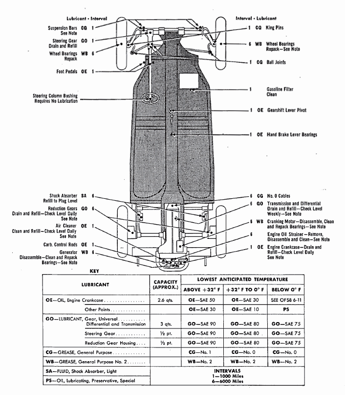
Figure 4—Lubrication Order
Always wipe clean metal surfaces on which a film of lubricant must be maintained by manual application, before the film is renewed.
c. Cleaning. Use SOLVENT, dry-cleaning, or OIL, fuel, Diesel, to clean or wash all parts. Use of gasoline for this purpose is prohibited. After washing, dry all parts thoroughly before applying lubricant.
d. Lubrication Notes on Individual Units and Parts. The following instructions pertain to lubrication and service of individual units and parts.
(1) AIR CLEANERS. Daily, check level and refill engine air cleaner
oil reservoir to bead level with used OIL, crankcase, or OIL, engine,
SAE 30, above +32°F and SAE 10 from +32°F to 0°F. From 0°F
to -40 °F, use OIL, hydraulic, or FLUID, shock absorber, light. Below
-40°F, remove oil and operate dry. Every 1,000 miles (daily under
extremely dusty conditions) remove air cleaners, wash all parts, and
refill.
(2) CRANKCASE. Daily, check level and refill to "FULL" mark with OIL, engine SAE 50, above +32°F or SAE 30 from +32°F to 0°F. Below 0°F, refer to paragraph 25 in this manual or to OFSB 6-11. Every 1,000 miles, remove crankcase drain plug and completely drain case. Drain only when engine is hot. After thoroughly draining, replace drain plug and refill crankcase to "FULL" mark on gage with correct lubricant to meet temperature requirements. Run engine a few minutes and recheck oil level. Be sure pressure gage indicates oil is circulating.
(3) OIL STRAINER. Every 6,000 miles, or more often, if strainer becomes clogged, disassemble and clean strainer.
(4) GEAR CASES (TRANSMISSION AND DIFFERENTIAL). Weekly,
check level with vehicle on level ground, and if necessary, add lubricant to plug level at all times. Every 6,000 miles, drain and refill.
Drain only after operation when gear lubricant is.warm. Refill with
LUBRICANT, gear, universal, SAE 90, above +32 °F, SAE 80 from
+32°F to 0°F, or SAE 75 below 0°F.
(5) WHEEL BEARINGS. Remove bearing cone assemblies from hub. Wash bearings, cones, spindle, and inside of hub, and dry thoroughly. Do not use compressed air. Inspect bearing races and replace if damaged. Wet the spindle and inside of hub and hub cap with GREASE, general purpose, No. 2 to a maximum thickness of yia inch only, to retard rust. Lubricate bearings with GREASE, general purpose, No. 2 with a packer, or by hand, kneading lubricant into all spaces in the bearing. Use extreme care to protect the bearings from dirt, and immediately reassemble and replace wheel. Do not fill hub or hub cap. The lubricant in the bearing is sufficient to provide lubrication until the next service period. Any excess might result in leakage into the drum. Adjust bearings in accordance with instructions in paragraph 103.
(6) DISTRIBUTOR. Every 1,000 miles, lubricate distributor shaft
with six to eight drops of OIL, engine SAE 30 above -f-32°F, SAE
10 from +32°F to 0°F, or OIL, lubricating, preservative, special below 0°F. Every 6,000 miles, wipe the distributor breaker cam lightly
with GREASE, general purpose, No. 1 above +32°F and No. 0
below +32 °F. Also lubricate the breaker arm pivot with one to two
drops of OIL, engine SAE 30 above +32°F, SAE 10 from +32°F
to 0°F, or OIL, lubricating, preservative, special below 0°F.
(7) OILCAN POINTS. Every 1,000 miles, lubricate carburetor
linkage, foot pedals, hand brake lever and bearing linkage, gearshift
lever, engine compartment hinges, windshield, rubbing parts with OIL,
engine SAE 30 above +32°F, SAE 10 from +32°F to 0°F, or OIL,
lubricating, preservative, special below 0°F.
(8) POINTS NOT TO BE LUBRICATED. These points are the clutch release bearing and steering column bushing.
(9) POINTS TO BE SERVICED AND/OR LUBRICATED BY ORDNANCE MAINTENANCE PERSONNEL ONLY.
(a) Cranking Motor. Every 6,000 miles; remove cranking motor
and clean drive. While cranking motor is disassembled, wash the
bearings with SOLVENT, dry-cleaning or OIL, fuel, Diesel. Repack
bearings with GREASE, general purpose, No. 2.
(b) Generator. Every 6,000 miles, remove generator and clean.
While generator is disassembled, wash the bearings with SOLVENT,
dry-cleaning or OIL, Diesel and repack bearings with GREASE,
general purpose, No. 2.
e. Reports and Records. Report unsatisfactory performance of material to the ordnance officer responsible for maintenance. A record of lubrication may be maintained in the Duty Roster (W.D., A.G.O. Form No. 6).
PART THREE—MAINTENANCE INSTRUCTIONS
Section VIII. FIRST ECHELON PREVENTIVE MAINTENANCE SERVICES
20. PURPOSE.
a. To insure mechanical efficiency, it is necessary that the vehicle be systematically inspected at intervals each day it is operated, and weekly, so that defects may be discovered, and corrected, before they result in serious damage or failure. Certain scheduled maintenance services will be performed at these designated intervals. The services set forth in this section are those performed by driver or crew, before operation, during operation, at halt and after operation, and weekly.
b. "Driver Preventive Maintenance Services" are listed on the
back of "Driver's Trip Ticket and Preventive Maintenance Service
Record," W.D. Form No. 48 to cover vehicles of all types and models.
Items peculiar to specific vehicles, but not listed on W.D. Form No. 48,
are covered in manual procedures under the items to which they
pertain. Certain items listed on the form, that do not pertain to the
vehicle involved, are eliminated from the procedures as written into
the manual. Every organization must thoroughly school each driver
in performing the maintenance procedures set forth in manuals
whether they are listed specifically on W.D. Form No. 48, or not.
c. The items listed on W.D. Form No. 48 that apply to the
Volkswagenwerk are expanded in this manual to provide specific
procedures for accomplishment of the inspections and services. These
services are arranged to facilitate inspection and conserve the time
of the driver, and are not necessarily in the same numerical order as
shown on W.D. Form No. 48. The item numbers, however, are
identical with those shown on that form.
d. The general inspection of each item applies to any supporting
member or connection, and generally includes a check to see if the
item is in good condition, correctly assembled, secure, or excessively
worn.
e. The inspection for "good condition" is usually an external
visual inspection to determine whether or not the unit is damaged
beyond safe or serviceable limits. The term "good condition" is explained further by the following: not bent or twisted, not chafed or
burned, not broken or cracked, not bare or frayed, not dented or
collapsed, not torn or cut.
f. The inspection of a unit to see that it is "correctly assembled"
is usually an external visual inspection to see if it is in its correctly
assembled position in the vehicle.
g. The inspection of a unit to determine if it is "secure" is usually
an external visual examination, a wrench, hand-feel,. or a pry-bar
check for looseness. Such an inspection should include any brackets,
lock washers, lock nuts, locking wires, or cotter pins used in assembly.
h. "Excessively worn" will be understood to mean worn close to, or beyond, serviceable limits, and likely to result in a failure if not replaced before the next scheduled inspection.
i. Any defects, or unsatisfactory operating characteristics beyond the scope of first echelon to correct, must be reported at the earliest opportunity to the designated individual in authority.
21. BEFORE-OPERATION SERVICE.
a. Purpose. This inspection schedule is designed primarily as a check to see that the vehicle has not been tampered with, or sabotaged, since the After-operation Service was performed. Various combat conditions may have rendered the vehicle unsafe for operation, and it is the duty of the driver to determine whether or not the vehicle is in condition to carry out any mission to which it may be assigned. This operation will not be entirely omitted, even in extreme tactical situations.
b. Procedures. Before-operation Service consists of inspecting
items listed below, according to the procedure described, and correcting, or reporting, any deficiencies. Upon completion of the service, results should be reported promptly to the designated individual in
authority.
(1) ITEM 1, TAMPERING AND DAMAGE. Examine exterior of
vehicle, engine, wheels, brakes, and steering control for any damage
by falling debris, shell fire, sabotage, or collision since parking the
vehicle.
(2) ITEM 2, FIRE EXTINGUISHER. Inspect portable fire extinguisher to see that it is present, full, securely mounted, and nozzle clean. Check contents by removing filler plug.
(3) ITEM 3, FUEL AND OIL. Check fuel and oil levels, replenish supply as necessary. NOTE: Report any unusual losses.
(4) ITEM 4, ACCESSORIES AND DRIVES. Examine carburetor, fuel pump, generator, cranking motor, air cleaner, and blower for looseness, damage, or leaks. Check generator belt for %o- to %-inch deflection.
(5) ITEM 6, LEAKS, GENERAL. Look under vehicle and in engine compartment for any indication of fuel or oil leaks. Examine crankcase, transmission, spider gear housing, fuel tank and lines for leaks. Trace any leak to its source and correct or report it.
(6) ITEM 8, CHOKE. While starting the engine, check operation
of the choke linkage to see that the choke valve opens and closes
properly.
(7) ITEM 7, ENGINE WARM-UP. Start engine, noting if cranking
motor has adequate cranking speed and engages, and disengages,
properly without unusual noise. As the engine warms up, reset the
choke as required to prevent overchoking and dilution of engine oil.
Both red light (ammeter) and green light (oil pressure) must go out
when engine starts. If either light continues to burn with engine running, stop engine and investigate or report trouble.
(8) ITEM 9, INSTRUMENTS. CAUTION: Both green light (oil
pressure) and red light (ammeter) must burn when ignition switch
is turned on.
(a) Oil Pressure Indicator. Oil pressure is indicated by green
light going out as soon as engine is started. If light continues to burn
after engine is started, stop engine and investigate or report trouble.
(b) Ammeter. Red light indicator burns red as soon as ignition
switch is turned on and must go out as engine runs above idling speed.
If red light continues to burn after engine is running above idling
speed, stop engine and investigate, or report, trouble.
(9) ITEM 10, HORN AND WINDSHIELD WIPERS. If tactical situation permits, sound horn for proper tone. Examine windshield wipers for proper operation. See that wipers are securely mounted and blades contact glass through their full stroke.
(10) ITEM 11, GLASS AND REAR VIEW MIRROR. Clean and inspect all glass for cracks and discoloration.
(11) ITEM 12, LAMPS AND REFLECTORS. With all light switches
at "ON" position, including blackout and stop lights, inspect all lights
to see that they are securely mounted, burning, clean, and that they
go out when switch is turned off.
(12) ITEM 13, WHEEL AND STUD NUTS. Inspect all wheel stud
nuts to see that they are present and secure. Be sure that hub caps
are securely mounted.
(13) ITEM 14, TIRES. Examine tires, including spare, for flats or
low pressure. Correct pressure for front tires is 21 pounds; for rear
tires 27 pounds, cool. Inspect tires, wheels, and valve caps for good
condition and mounting. Spare should be mounted on road wheel at
90-day intervals.
(14) ITEM 16, STEERING LINKAGE. Examine steering gear hous¬ing for leaks or loose mounting bolts and all linkage for wear or
damage.
(15) ITEM 17, FENDERS. Make sure all fenders are in good condition and securely mounted.
(16) ITEM 18, TOWING CONNECTIONS. Towing hooks must be in serviceable condition and latches operate freely.
(17) ITEM 19, BODY AND TOP. Inspect body, top, and doors for
looseness or damage. See that top is securely attached to windshield
and body and that it is in good condition.
(18) ITEM 20, DECONTAMINATOR. Decontaminator must be present, fully charged, and securely mounted. Check contents by removing filler plug.
(19) ITEM 21, TOOLS AND EQUIPMENT. See that all tools are in
good condition and properly stowed or mounted.
(20) ITEM 22, ENGINE OPERATION. With the engine running
above idling speed, red light (ammeter) and green light (oil pressure)
must go out. If either light burns, stop engine and investigate or report
trouble. Accelerate and decelerate engine a few times and listen for
any unusual vibration or noise.
(21) ITEM 23, DRIVER'S PERMIT AND FORM 26. Driver must have
his operator's permit on his person. See that Form No. 26 (accident-
report) is present, legible, and safely stowed.
22. DURING-OPERATION SERVICE.
a. Purpose. While vehicle is in motion, listen for such sounds as
rattles, knocks, squeals, or hums that may indicate trouble. Look for
indications of trouble in air cooling system and smoke from any part
of the vehicle. Be on the alert to detect any odor of overheating components or units such as generator,, brakes, or clutch; fuel vapor from a leak in fuel system, exhaust gas, or other signs of trouble. Each time
the brakes are used, gears shifted, or vehicle turned, consider this a
test, and notice any unsatisfactory or unusual instrument indications
that may signify possible trouble in system to which the instrument
pertains.
b. Procedures. During-operation Services consist of observing items listed below according to the procedures following the instructions in each item, and investigating any indications of serious trouble. Notice minor deficiencies to be corrected, or reported, at earliest opportunity, usually next scheduled halt.
(1) ITEM 27, FOOT, AND HAND BRAKES. Apply foot brake and
observe whether or not it will stop the vehicle effectively without
excessive side pull. Be sure there is 1 Vi-inch floorboard to pedal
clearance in applied position. Hand brake should hold vehicle se
curely on grade with one-third ratchet travel in reserve, and latch
securely in applied position.
(2) ITEM 28, CLUTCH. While shifting gears note any chatter, grabbing, or squealing of the clutch. Observe if clutch slips under load. Clutch pedal should have %-inch free-pedal travel before clutch starts to disengage.
(3) ITEM 29, TRANSMISSION. Transmission gears should shift
smoothly, operate without unusual noise, and not slip out of mesh.
Stop vehicle and investigate if there is any unusual noise in trans
mission.
(4) ITEM 31, ENGINE AND CONTROLS. Driver should always be
on the alert for any deficiencies in engine operation such as lack of
power on acceleration, excessive smoke, misfiring, or overheating.
Note any binding or unusual operation of the engine control linkage.
(5) ITEM 32, INSTRUMENTS.
(a) Oil Pressure. Oil pressure indicator green light must not burn
after engine starts. If light continues to burn with engine running, stop
engine and investigate or report trouble.
(b) Ammeter. Red light must not burn with engine running above
idling speed. If light continues to burn with engine running above
idling speed, stop engine and investigate or report trouble.
(c) Speedometer. Speedometer should register vehicle speed, and odometer should record accumulated kilometers.
(6) ITEM 33, STEERING GEAR. Test steering for wander, shimmy, looseness, binding, or pulling to either side of the road.
(7) ITEM 34, RUNNING GEAR. Listen for any unusual noise
in wheels, axles, or suspensions that would indicate looseness, damage,
lack of lubrication, or under-inflated tires.
(8) ITEM 35, BODY AND TOP. Be on the alert for noise that would indicate loose top fastenings, doors, seats, or attachments.
23. AT-HALT SERVICE.
a. Importance. The At-halt Service may be regarded as minimum battle maintenance and should be performed under all tactical
conditions, even though more extensive maintenance services must
be slighted or omitted altogether.
b. Procedures. At-halt Service consists of investigating any deficiencies noted during operation, inspecting items listed below according to the procedures following the items, and correcting any deficiencies found. Deficiencies not corrected should be reported promptly to designated individual in authority.
(1) ITEM 38, FUEL AND OIL. Check to see that there is adequate fuel and engine oil to operate to next scheduled stop. Replenish supply if needed.
(2) ITEM 39, TEMPERATURES, HUBS, BRAKE DRUMS, TRANSMISSION, AND AXLE. Hand-feel wheel hubs, brake drums, transmission, differential, and rear wheel final reduction gear housing for abnormal temperatures. (3) ITEM 42, SUSPENSIONS. Inspect torsion arms, traverse spring housings, and center housings for damage and loose mountings. Inspect shock absorbers for loose mountings and worn linkage. Check front axle to front frame head for secure mounting.
(4) ITEM 43, STEERING LINKAGE. Inspect Pitman arm and linkage for looseness or damage.
(5) ITEM 44, WHEEL STUD NUTS. Inspect all wheel stud nuts to
see that they are present and secure. See that hub caps are securely
mounted.
(6) ITEM 45, TIRES. Inspect for flats or low pressure, missing
valve caps, cuts, and bruises. Normal pressure for front tires is 21
pounds; for rear, 27 pounds, cooL
(7) ITEM 46, LEAKS, GENERAL. Look in engine compartment,
under vehicle and fuel tank, for indications of fuel or oil leaks. Trace
all leaks to their source, and correct or report any leaks found.
(8) ITEM 51, BODY AND TOP. Inspect body, doors, windshield, top, and seats for good condition.
(9) ITEM 47, ACCESSORIES AND BELTS. Inspect all accessories for
loose mountings and incorrect alinement. Generator and blower belt
must not be frayed or broken, and should have %<-,- to %-inch
deflection (finger pressure).
(10) ITEM 48, AIR CLEANER. If vehicle has been operated under
extremely dusty or sandy conditions, examine element for excessive
dirt and oil level. Service as necessary.
(11) ITEM 49, FENDERS. Inspect fenders for loose mountings and damaged condition.
(12) ITEM 50, TOWING CONNECTIONS. Towing hooks must be in good condition with latches working properly.
(13) ITEM 52, GLASS. Clean windshield, rear vision mirrors, and light lenses. Inspect for looseness and damage.
24. AFTER-OPERATION AND WEEKLY SERVICE.
a. Purpose. After-operation Service is particularly important,
because at this time, the driver inspects his vehicle to detect any
deficiencies that may have developed, and corrects those he is permitted to handle. He should report the results of his inspection
promptly to the designated individual in authority. If this schedule
is performed thoroughly, the vehicle should be ready to roll again on
a moment's notice. The Before-operation Service, with a few exceptions, is then necessary only to ascertain whether or not the vehicle
is in the same condition in which it was left, upon completion of the
After-operation Service. The After-operation Service should never be
entirely omitted, even in extreme tactical situations, but may be
reduced to the bare fundamental services outlined for, the At-halt
Service, if necessary.
b. Procedures. When performing the After-operation Service,
the driver must remember to consider any irregularities noticed
during the day in the Before-operation, During-operation, and At-halt
Services. The After-operation Service consists of inspecting and
servicing the following items: (Those items of the After-operation
Service that are marked by an asterisk (*) require additional weekly
services, the procedures for which are indicated in subparagraph (b) of each applicable item.)
(1) ITEM 55, ENGINE OPERATION. Before stopping engine, check
for smooth idle. Accelerate and decelerate a few times noting any
unusual noise or excessive smoking. Investigate any deficiencies noted
during operation.
(2) ITEM 56, INSTRUMENTS. Before stopping engine, inspect oil
pressure indicator to see that the green light remains out while engine
is running. See that red light (ammeter) goes out with engine
running above idling speed.
(3) ITEM 57, HORN AND WINDSHIELD WIPERS. If tactical situation permits sound horn for proper tone. Examine windshield wipers for proper operation and good blades.
(4) ITEM 54, FUEL AND OIL. Fill fuel tank, check engine oil level,
and if necessary fill to correct level with specified oil. See that any
fuel or oil used from spare cans is replenished.
(5) ITEM 58, GLASS AND REAR VIEW MIRRORS. Inspect windshield for damage or looseness, clean glass, and adjust rear view
mirrors.
(6) ITEM 59, LAMPS (LIGHTS) AND REFLECTORS. Observe
whether or not the lights operate properly with the switches at all
of the "ON" positions, and go out when switched off. Operate brake
pedal and observe whether or not stop light functions properly.
Observe whether or not foot-operated beam deflector switch operates
headlights properly. Inspect all lenses and warning reflectors for
looseness or damage; clean if necessary.
(7) ITEM 60, FIRE EXTINGUISHER. Examine portable fire extinguisher to see that it is full, nozzle clean, and securely mounted.
To determine contents, remove filler plug.
(8) ITEM 61, DECONTAMINATOR. Decontaminator must be fully
charged, securely mounted, and valve closed. To determine contents,
Remove filler plug.
(9) ITEM 62, BATTERY.
(a) Inspect battery for leaks or damage, security of mountings,
and connections. Battery connections and mountings should be kept
clean and tight.
(b) Weekly. Examine battery for cracks and leaks, tighten all terminals and mountings, clean corroded terminals, and apply a coating of grease. Add clean water to bring level % inch above plates. In freezing weather do not add water until vehicle is to be started.
(10) ITEM 63, ACCESSORIES AND BELT. Examine carburetor, fuel pump, generator, cranking motor, air cleaner, and blower for looseness, damage, or leaks. Check generator belt for %0- to %-inch deflection.
(11) ITEM 64, ELECTRICAL WIRING. Inspect all accessible wiring and conduits to see that they are clean, secure, and properly supported.
(12) ITEM 65, *AIR CLEANERS AND BREATHER CAPS.
(a) If vehicle has been operated under extremely dusty or sandy
conditions, examine filter elements for clogged condition. Remove
and clean if necessary.
(b) Weekly. Remove and clean air cleaner element and sump.
Refill to proper oil level and tighten mountings securely. Clean oil
filler breather cap.
(13) ITEM 66, *FUEL FILTERS.
(a) Examine for dirt or sediment Clean if needed.
(b) Weekly. Close shut-off cock, remove filter bowl, and clean.
When replacing bowl be careful not to damage bowl gasket. Turn on
fuel cock and examine for leaks.
(14) ITEM 67, ENGINE CONTROLS. Examine engine and accessory controls for loose, worn, or binding linkage. Lubricate as necessary.
(15) ITEM 68, *TIRES.
(a) Inspect tires for correct pressure (21 pounds front, 27 pounds
rear, cool). Replace any missing valve caps and inspect for cuts,
bruises, fractures, or evidence of excessive wear. Remove any foreign
substance found in tire treads.
(b) Weekly. Inspect tires for evidence of abnormal wear and replace badly worn or otherwise unserviceable tires.
(16) ITEM 69, * SUSPENSION.
(a) Inspect shock absorbers and torque arms, clamps, and bolts for presence and secure mounting.
(b) Weekly. Inspect torque arms, torque shaft, and shock absorbers and linkage, for loose mountings, oil leaks, and condition.
Tighten all clamp and bracket bolts.
(17) ITEM 70, STEERING LINKAGE. Inspect steering arm, linkage,
and tie rod for damage or loose connections. Check for security and
presence of stop screws and bumper blocks.
(18) ITEM 73, LEAKS, GENERAL. Look under vehicle, in engine
compartment, and under fuel tank for evidence of leaks. Check
around rear wheel final reduction gear housings, transmission housing,
and torsion tube seals for leaks.
(19) ITEM 74, GEAR OIL LEVELS. Check transmission differential, and rear axle final reduction gear housings for lubricant levels. This should not be done until these units have cooled, at least enough to permit the hand to be held on them. Oil must not be more than y% inch below filler hole when cold, and not above bottom of filler hole when hot
(20) ITEM 76, FENDERS. Inspect all fenders to see that they are secure and in good condition. Tighten all loose mounting bolts.
(21) ITEM 77, TOWING CONNECTIONS. Inspect towing hooks and latches for security and condition.
(22) ITEM 78, BODY AND TOP AND W/S. Inspect body, doors,
seats, windshield, and top for security and mountings. Check top-to-
body fasteners, see that doors operate properly and that seats are
secure. Check to see that top-to-windshield fasteners are present and
secure.
(23) ITEM 82, *TIGHTEN.
(a) Tighten wheel stud and axle nuts, or any other assembly or mounting nuts or screws that inspection indicates need tightening.
(b) Weekly. Tighten suspension units, engine mountings, gear
cases, steering connections,' body bolts, accessories and attachments
or any other points where inspection or experience has indicated the
need on a weekly or mileage basis.
(24) ITEM 83, *LUBRICATE AS NEEDED.
(a) Oil and lubricate all parts as required when performing
After-operation Service. For specific intervals and lubricants to be
used, refer to figure 4, paragraph 19.
(b) Weekly. Lubricate all parts indicated on figure 4 as requiring
attention on a weekly, or mileage, basis, or any other points that
inspection or experience indicates the need of lubrication at this time.
(25) ITEM 84, *CLEAN ENGINE AND VEHICLE.
(a) Clean dirt and trash from inside of body. Remove excessive dirt and grease from exterior of engine.
(b) Weekly. Wash vehicle when possible. While washing, remove
drain caps from floor to allow interior to drain. Observe for bright
spots that would cause glare.
(26) ITEM 85, *TOOLS AND EQUIPMENT.
(a) Inspect all tools for serviceability.
(b) Weekly. Clean, condition, and stow all tools and equipment. Replace missing tools or equipment by cannibalization.
Section IX SECOND ECHELON PREVENTIVE MAINTENANCE
25. SECOND ECHELON PREVENTIVE MAINTENANCE SERVICES.
a. Responsibility. Regular scheduled maintenance inspections and services are a preventive maintenance function of the using arms, and are the responsibility of commanders of operating organizations.
(1) FREQUENCY. The frequency of the preventive maintenance
services outlined herein is considered a minimum requirement for
normal operation of vehicles. Under unusual operating conditions,
such as extreme temperatures, dusty or sandy terrain, it may be
necessary to perform certain maintenance services more frequently.
(2) FIRST ECHELON PARTICIPATION. The drivers should accompany their vehicles and assist the mechanics while periodic
second echelon preventive maintenance services are performed. Ordinarily the driver should present the vehicle for a scheduled preventive maintenance service in a reasonably clean condition, that is, it
should be dry and not caked with mud or grease to such an extent
that inspection and servicing will be seriously hampered. However,
the vehicle should not be washed or wiped thoroughly clean, since
certain types or defects, such as cracks, leaks, and loose or shifted
parts or assemblies are more evident if the surfaces are slightly
soiled or dusty.
(3) REFERENCES. If instructions other than those contained in the general procedures in subparagraph (4) or the specific procedures in subparagfaph (5) which follow, are required for the correct performance of a preventive maintenance service or for correction of a deficiency, other sections of this manual pertaining to the item involved, or a designated individual in authority should be consulted.
(4) GENERAL PROCEDURES. These general procedures are basic
instructions which are to be followed when performing the services
on the items listed in the specific procedures. NOTE: The second
echelon personnel must be thoroughly trained in these procedures so
that they will apply them automatically.
(a) When new or overhauled subassemblies are installed to cor¬rect deficiencies, care must be taken to see that they are clean,
correctly installed, properly lubricated, and adjusted.
(b) When installing new lubricant retainer seals, a coating of the
lubricant should be wiped over the sealing service of the lip of the
seal. When the new seal is a leather seal, it should be soaked in
SAE 10 engine oil (warm if practicable) for at least 30 minutes.
Then, the leather lip should be worked carefully by hand, before
installing the seal. The lip must not be scratched or marred.
(c) The general inspection of each item applies also to any supporting member or connection, and usually includes a check to see
whether or not the item is in good condition, correctly assembled,
secure, or excessively worn. The mechanic must be thoroughly
trained in the following explanations:
1. The inspection for "good condition" is usually an external
visual inspection to determine if the unit is damaged beyond safe or
serviceable limits. The term "good condition" is explained further by
the following: not bent or twisted, not chafed or burned, not broken
or cracked, not bare or frayed, not dented or collapsed, not torn or cut.
2. The inspection of a unit to see that it is "correctly assembled"
is usually an external visual inspection to see whether or not it is in
its normal assembled position in the vehicle.
3. The inspection of a unit to determine if it is "secure" is usually an external visual examination, a wrench, hand-feel or a pry-bar check for looseness. Such an inspection should include any brackets, lock washers, lock nuts, locking wires, or cotter pins used in assembly.
4. "Excessively worn" will be understood to mean worn close-to, or
beyond, serviceable limits, and likely to result in a failure if not
replaced before the next scheduled inspection.
(d) Special Services. These are indicated by repeating the item numbers in the columns which show the interval at which the services are to be performed, and show that the parts, or assemblies, are to receive certain mandatory services. For example, an item number in one or both columns opposite a tighten procedure, means that the actual tightening of the object must be performed. The special services include:
1. Adjust. Make all necessary adjustments in accordance with
the pertinent section of the vehicle operator's manual, special
bulletins, or other current directives.
2. Clean. Clean units of the vehicle with dry-cleaning solvent
to remove excess lubricant, dirt, and other foreign material. After
the parts are cleaned, rinse them in clean fluid and dry thoroughly.
Take care to keep the parts clean until reassembled, and be certain
to keep cleaning fluid away from rubber or other material that it
would damage. Clean the protective grease coating from new parts
since this material is not a good lubricant.
3. Special Lubrication. This applies either to lubrication operations that do not appear on the vehicle Lubrication Guide and to
items that do appear on the Guide but should be performed in connection with the maintenance operations if parts have been dis¬
assembled for inspection or service.
4. Serve. This usually consists of performing special operations,
such as replenishing battery water, draining and refilling units with
oil, and cleaning or changing the oil filter or cartridge.
5. Tighten. All tightening operations should be performed with
sufficient wrench torque (force on the wrench handle) to tighten the
unit according to good mechanical practice. Use torque-indicating
wrench where specified. Do not overtighten, as this may strip threads or cause distortion. Tightening will always be understood to include the correct installation of lock washers, lock nuts, and cotter pins provided to secure the tightening.
(e) When conditions make it difficult to perform the complete
preventive maintenance procedures at one time, they can sometimes
be handled in sections, planning to complete all operations within the
week if possible. All available time at halts, and in bivouac areas,
must be utilized, if necessary, to assure that maintenance operations
are completed. When limited by the tactical situation, items with
special services in the columns, should be given first consideration.
(f) The numbers of the preventive maintenance procedures that
follow are identical with those outlined on W.D. AGO Form No. 461,
which is the Preventive Maintenance Service Work Sheet for
Wheeled and Half-track Vehicles. Certain items on the work sheet
that do not apply to this vehicle are not included in the procedures
in this manual. In general, the numerical sequence of items on the
work sheet is followed in the manual procedures, but in some instances there is deviation for conservation of the mechanic's time
and effort.
(5) SPECIFIC PROCEDURES. The procedures for performing each item in the 1,000-mile (monthly) and 6,000-mile (six-month) maintenance procedures are described in the following chart. Each page of the chart has two columns at its left edge corresponding to the 6,000-mile and the 1,000-mile maintenance respectively. Very often it will be found that a particular procedure does not apply to both scheduled maintenances. In order to determine which procedure to follow, look down the column corresponding to the maintenance due, and wherever an item number appears, perform the operations indicated opposite the number.
ROAD TEST NOTE: When the tactical situation does not permit a full road test, perform those operations which will require little or no movement of the vehicle. When a road test is possible, it should be for preferably three miles but not over five miles.
6,000 Mile /1,000 Mile
(Six Month)/ (Monthly)
Malnt. /Malnt.
1/1 Before-operation Service. Perform the Before-operation Service as directed in paragraph 21.
3/3 Dash Instruments and Cages. Observe as follows: OIL PRESSURE. Green light must burn as soon as ignition switch is turned on and go out as soon as engine starts. CAUTION: If green light continues to burn while engine is running, stop engine immediately and investigate the cause. AMMETER. Red light must burn when ignition switch is turned "ON," and go out as engine speed increases above idling speed. CAUTION: If red light continues to burn with engine running above idling, stop engine immediately and investigate cause. SPEEDOMETER. Observe speedometer to see that it registers vehicle speed and odometer records ac¬cumulating mileage.
4/4 Horn, Mirror and Windshield Wipers. If tactical situation permits test horn for proper operation and tone. Examine windshield wipers to see that they are operating properly. Adjust the rear vision mirror.
5/5 Brakes, Foot and Hand. Apply foot brake during operation to test for smooth effective braking. Vehicle should stop within reasonable distance without side pull. Pedal to floorboard clearance should be at least 1 Vi inches with brake in applied position. Apply hand brake with vehicle on reasonable in¬cline. Brake should hold vehicle securely with % ratchet travel in reserve, and should latch in applied position.
6/6 Clutch. While shifting gears, note any drag, chatter or squealing of the clutch. Test for slipping while under load. Pedal free travel before meeting resistance should be 3A inch.
7/7 Transmission. Shifting lever should operate freely, gears operate without any unusual noises that would indicate damage or lack of lubrication and not slip out of mesh.
8/8 Steering. While driving vehicle turn steering wheel full travel both directions (road conditions per¬mitting) and observe any looseness or binding. Note any tendency to wander, shimmy or pull to one side. When the vehicle is stopped, inspect the steer¬ing wheel and column for good condition and secure mountings.
9/9 Engine. Listen for knocks and rattles as engine is accelerated, decelerated, and while it is under both light and heavy loads. Note any tendency to stall while shifting. A slight ping during fast acceleration is normal, continued or a heavy ping may indicate early timing, heavy accumulation of carbon.
10/10 Unusual Noises. Be on the alert continually for unusual noises that would indicate worn or loose parts or lack of lubrication, damage or malfunctioning units in the power train, body or wheels.
13/13 Temperatures. Cautiously hand feel hubs, brake drums, transmission case, and rear wheel final "re¬duction gear housings for evidence of overheating.
14/14 Leaks. Look under vehicle in engine compartment, and under fuel tank for engine oil, gear oil, or fuel leaks. Determine the source of any leaks found and correct, or report them.
MAINTENANCE OPERATIONS Raise Vehicle Block Safely
16/16 Gear Oil Levels and Leaks. Inspect the axle housing, transmission, and rear wheel final reduction gear housings to see that the lubricant is at the proper level, in good condition and not leaking. NOTE: A safe range level is from the lower edge of the filler hole when hot to V2 inch below when cold.
17/17 Unusual Noises. With engine running, observe as follows: ENGINE BELT AND ACCESSORIES. Accelerate and decelerate engine momentarily, and listen for any unusual noises in these units that might indicate damaged, loose, or excessively worn engine parts, drive belt, or accessories. TRANSMISSION AND REAR WHEEL SPIDER GEAR DRIVES. With transmission in gear, run at a constant, moderate speed, and listen for any unusual noises that would indicate damaged, loose, exces¬sively worn parts, or lack of lubrication.
18/18 Cylinder Head. Inspect the cylinder head and fins for good condition and blow or brush off all dirt and foreign matter.
20/20 Remove spark plugs and clean thoroughly on sandblast cleaner (if available). Inspect insulators for cracks and electrodes for excessive burning. If sandblast cleaner is not available, install new or reconditioned plugs. Reset the gap, to 0.025 inch by bending grounded electrode only. Reinstall using new gaskets.
22/22 Battery, Cables, Hold-down, Carrier, Record Gravity and Voltage. Inspect battery case for cracks and leaks. Clean top of battery. Inspect cables, terminals, bolts, posts, straps and hold-downs for good condition. Test specific gravity and voltage and record on W.D. AGO Form No. 461. Specific gravity readings below 1.225 at normal temperature indicate battery should be recharged or replaced. Electrolyte level should be above top of plates and may extend 3/8 inch above plates.
22/ Perform high-rate discharge test according to instructions for "condition" test which accompany test instrument and record voltage on W.D. AGO Form No. 461. Cell variation should not be more than 30 percent. NOTE: Specific gravity must be above 1.225 to make this test.
22/22 Bring electrolyte to proper level by adding distilled or clean water. Clean entire battery and carrier. Repaint carrier if corroded. Clean battery cable terminals, terminal bolts and hold-downs carefully to avoid damage to battery.
23/23 Crankcase, Leaks, Oil Level. With engine idling, examine crankcase, valve cover, timing gear cover, and clutch housing for oil leaks. Stop engine and after oil has drained into the crankcase, see whether or not the oil is at the proper level. If oil change is due, or condition of the oil indicates the necessity, drain crankcase and refill to correct level with specified oil. See Lubrication Guide (par. 19).
24/ Oil Cooler and Lines. Remove oil cooler, and thoroughly clean in dry-cleaning solvent. Inspect cooler and all oil lines to see that they are not clogged or damaged. Install cooler making sure all gaskets and lines are secure and not leaking.
26/26 Fan, Blower, and Shroud. Inspect fan and shroud for good condition, alinement, and loose attaching bolts.
27/27 Generator, Cranking Motor, and Switch. Inspect generator and cranking motor for damage, loose mounting bolts, and loose wiring connections.
27/ SERVE. Remove generator and cranking motor inspection covers and inspect commutators and brushes to see that they are in good condition, that brushes are free in their holders, springs are not broken, and that all brush wires are in good con¬dition and secure.
CLEAN. If commutators are dirty, clean with flint paper 2/0, blow out accumulated dust with com¬pressed air. Replace cover bands and tighten all mounting bolts and electrical connections securely.
29/29 Drive Belt and Pulley. Inspect drive belt for evidence of fraying, excessive wear, deterioration, and correct tension. Correct tension is %c>- to %-inch deflection finger pressure. See that drive pulley is securely mounted and in good condition.
31/31 Distributor. Clean distributor cap and housing. Remove cap and examine rotor arm and cap for cracks, carbon runners, or excessively burned elec¬trodes. Inspect points for proper gap, alinement, burned, or pitted condition. If points are slightly burned, reface on a fine stone and adjust gap to 0.020 inch (par, 45 c).
31/ Test centrifugal advance by finger rotation for normal range or movement and return when released without binding.
32/32 Coil and Wiring. Inspect coil for cracked insulation or loose mounting bolts. Examine all wiring for good condition, cleanliness, correct assembly, tight connections, and make sure it is not chafingagainst other parts. Clean all exposed ignition wiring with a dry cloth.
33/33 Manifolds. Inspect intake and exhaust manifolds for cracks, gasket leaks or loose mounting bolts. Tighten as necessary.
./19Valve Mechanism. Adjust to 0.006 inch intake, 0.008 inch exhaust, engine cold, only when need is indicated by excessive noise or faulty engine performance.
19/. ADJUST. Adjust valve stem to rocker arm clearance to 0.006 inch intake, 0.008 inch exhaust, engine cold. See instructions, paragraph 46. Inspect valves, rocker arms, shaft, springs, and retainers to see that they are in good condition, correctly assembled and secure, and make sure oil is being delivered to valve mechanism. Inspect valve rocker arm cover gasket for serviceability and replace if necessary.
34/34 Air Cleaner. Remove air cleaner and disassemble. Thoroughly clean element and oil reservoir in dry-cleaning solvent. Refill with engine oil to level plug in body and reassemble, tightening all mounting connections securely.
36/36 Carburetor (Choke, Linkage, and Throttle). See that these items are in good condition, correctly assembled and securely installed, that the car¬buretor does not leak and that all shafts and linkage open and close choke and throttle valves when operated.
37/37 Fuel Filters, Screens, and Lines. Close fuel valve, remove the filter bowl and screen. Open valve, drain sediment from tank until fuel runs clear, clean bowl and screen and reassemble filter. CAUTION: See that filter bowl gasket is not damaged, turn on fuel and check for leaks.
38/38 Fuel Pump. See that fuel pump is securely mounted to engine base and that all lines are in good con¬dition and secure.
38/. Attach pressure gage to pressure side of pump and start engine and after starting engine in item 39, see that pressure is 2 Vz to 4 pounds at idle speed.
39/39 Cranking Motor. Start engine, note if action of cranking motor is satisfactory, particularly that starting drive engages and disengages properly without unusual noise and has adequate cranking speed to start engine readily. As engine' starts, observe if all instruments are operating properly.
40/40 Leaks, Engine Oil, or Fuel. With engine running, inspect all units serviced for fuel or oil leaks. Trace any leaks to their source and correct or report them.
41/41 Ignition Timing. With engine running at idle speed, connect neon light and see if ignition timing is cor¬rect (par. 45 e). Accelerate engine and note if cen¬trifugal advance is operating correctly.
41/. ADJUST. Adjust timing, follow instructions in paragraph 45 e.
42/42 Engine I«IIc. Adjust carburetor to the degree that engine idles smoothly at normal idling speed and does not stop after acceleration (par. 64 b).
47/47 Tires. Observe if all valve stems are in good condition and in correct position. Replace leaky valve cores or missing caps. Examine tires for cuts, bruises, breaks, blisters and irregular tread wear. Remove all embedded glass, nails or other foreign substances from tread. Inflate tires to 21 pounds front, and 27 pounds rear, cold pressure. Mount spare tire on road wheel at intervals not exceeding 90 days.
48/ Rear Brakes. Remove rear wheels, hubs, and drums, and service as follows: On 6,000-mile main¬tenance service, the several wheel bearing and brake items up to 52 are group services and overlap. Perform in best order for economy of time and orderly reassembly.
48/ Drum, Supports, Cables, and Levers. Thoroughly clean and inspect drums for excessive wear or scores. Inspect backing plates for loose mountings or damaged condition. Note that cables and levers work freely and the brake shoes return to their stops.
./49 Rear Brake Shoes, Linings, Linkage, Guides and Anchors. Remove right rear hub and drum for in¬spection of brake linings to determine whether or not they should be replaced. If linings on this wheel brake must be replaced, remove all wheels and service the brakes similarly, being sure to lubricate and adjust all removed bearings, and clean drums, shoes, linings, and backing plates.
49 While rear wheels are removed inspect linings to
see if they are in good condition, secure to brake
shoes, in good wearing contact with drums, free of
dirt or lubricant, and not excessively worn. Also
see that brake shoes are in good condition, properly
secured and guided by anchor bolts and springs, and
return to stops by retracting springs. Clean all dust
from linings with a wire brush, clean cloth or compressed air. Linings worn to rivet heads, or that
will not be serviceable until the next inspection,
should be replaced.
49/49 ADJUST. If linings are slightly worn, make minor brake shoe adjustment to components for wear. If new linings have been installed, adjust shoes by the major adjustment method as outlined in para¬graph 103. Brake shoes should have clearance of 0.010 inch at cam end of brake shoe.
52/52 Rear Wheels. Inspect wheels for good condition and without removal test for evidence of looseness of wheel bearing adjustment, dry or damaged bear¬ings. Inspect wheel studs, stud nuts, and brake supports for good condition and security. Check drums for lubricant leaks. Tighten wheel stud nuts.
52/. CLEAN. Disassemble wheel bearings and seals, clean, and inspect for damage.
SPECAL LUBRICATION. Lubricate wheel bearings, according to instructions in Lubrication Guide (par. 19), and replace rear wheels. Adjust wheel bearings (par. 103).
53/. Front Brakes. Remove front wheel and inspect and service as follows: On 6,000-mile maintenance service, the several wheel bearings and brake items up to 60 are group services and overlap. Perform in best order for economy of time and orderly reassembly.
53/. Front Drums and Supports. Thoroughly clean and inspect drums for excessive wear, scores on leaking grease seals. Inspect backing plates for loose mountings or damaged condition.
./54 Front Brake Shoes, Linings, Linkage, Guides, and Anchors. Remove front hub and drum for inspection of brake linings to determine whether or not they should be replaced. If linings on this wheel brake must be replaced, remove all wheels and service their brakes similarly, being sure to lubricate and adjust all removed bearings, and clean drums, shoes, linings, and backing posts.
54/. With front wheels removed, inspect linings to see if they are in good condition, riveted securely to brake shoes, in good wearing contact with drums, ; free of dirt or lubricant, and not excessively worn. Also see that brake shoes are in good condition, properly secured and guided by anchor bolts and springs, and return to cams by retracting springs. Clean all dust from linings with a wire brush, clean cloth, or compressed air. Linings worn to rivet heads or that will not be serviceable until the next inspec¬tion, should be replaced.
54/54 ADJUST. Adjust in same manner as item 49.
56/56 Front Suspension. Inspect front support arms for good condition, security, and equal deflection.
57/57 Steering. Observe steering gear, steering arm, drag link, tie rod, and steering connections for. good con¬dition, correct assembly, and secure mounting.
60/60 Front Wheels, Bearings and Seals. Inspect front wheels, seals, and bearings, for good condition in the same manner as item 52 for rear wheels.
60/. CLEAN AND LUBRICATE. Disassemble front wheel
bearings. Clean, inspect, lubricate, and replace wheels, bearings, and seals.
ADJUST. Adjust bearings and test for wheel shake. Lubricate according to lubrication guide.
61/61 Front Axle. Check to see that front axle to frame head bolts are present and secure. See that axle tubes are in position and are not damaged.
63/63 Engine Mountings, and Braces, Ground Straps, Side Pans. Inspect all mounting bolts, braces, side pans, and ground straps. See that they are in good condition, securely mounted, and all ground straps are secure and clean. Note that engine (rubber) caulking is present and in good condition.
64/64 Hand Brake, Ratchet, Pawl, and Linkage. Observe whether or not the hand brake pawl, linkage, and cables are in good condition and secure. See that the cables pass freely through the tunnels and do not chafe.
65/65 Clutch Pedal. Test pedal for free travel (3/<t inch) and examine linkage for wear, missing cotter pins and return spring for proper tension.
ADJUST. Adjust clutch pedal according to specifications, paragraph 56.
66/66 Brake Pedal, Free Travel, Linkage and Return Spring. Test pedal for free operation and pedal to toeboard reserve. Examine linkage for wear, missing cotter pins and return spring for proper tension. Pedal and toeboard clearance must not be less than lVi inch with brake in applied position.
71/71 Transmission and Differential, Mountings, Seals, and Linkage. Inspect transmission and differential . housing seals and gaskets for evidence of leakage. Examine all attaching bolts for looseness, and check shift mechanism for wear and damage. Tighten all mounting and bracket bolts.
77/77 Rear Suspension. Inspect rear torsion arms, brackets, connections, and mountings. Observe to see that arm to axle bolts are tight, that arms to torsion shafts are secure and both sides have equal deflection.
77/. TIGHTEN. All mounting and bracket bolts should be tightened.
78/78 Rear Shock Absorbers and Links. See that the shock absorber bodies are secured to frame, that the links which connect their arms to the axle are in good condition and secure. See that there are no fluid leaks.
78/. SERVE. Fill shock absorbers. See Lubrication Guide, paragraph 19.
80/80 Frame, Center Housing, and Side Rails. Inspect for good condition and secure mountings.
81/81 Wiring Conduits and Grommets. Inspect these items under cowl and in engine compartment to see that they are in good condition, properly supported, connected, and secure.
82/82 Fuel Tank, Fittings, and Lines. Examine fuel tank to see that it is in good condition, securely mounted and not leaking. Examine cap for plugged vent, tight fit, and note that filler neck is not damaged. Check fuel lines and fittings to see that they are in good condition, securely supported and not leaking.
84/84 Exhaust Pipes and Mufflers. Examine exhaust pipe and mufflers for loose mountings, loose connections, deterioration or evidence of leaks. Inspect tail pipe for obstructions or damage.
85/85 Lubricate. Lubricate all points of vehicle in accordance with instructions in this manual, Lubrica¬tion Guide (fig. 4), current lubrication bulletins or directives, and the following instructions:. Replace missing or damaged fittings, lines, or plugs. Refill units to correct level as soon as draining is com¬pleted, so units will not be operated without lubri¬cant. Do not apply more than specified amount of lubricant to generator or cranking motor; to do so, may cause a failure of the unit. Wipe off excess lubricant that may soil clothes and equipment or detract from the vehicle's appearance. Parts or assemblies that have been lubricated while dis¬assembled for inspection, gear cases that have been drained and refilled as mandatory items in the pro¬cedures, and those parts that have been indicated in procedures for special lubrication, may be omitted from the general lubrication of the vehicle.
86/86 Toe-in and Turning Stops. Lower vehicle to ground with front wheels in straight ahead position, and check the toe-in limit for from V& to Vi inch. Turn steering wheel limit in both directions and inspect the turning stops to see that they are present and securely welded and prevent the tires from rubbing against the vehicle.
91/91 Lamps, Lights, Head, Tail, Stop, and Blackout. With all light switches, including stop and blackout, at "ON" position, inspect lamps to se that they light properly, are clean and securely mounted. Ad¬just headlights for proper aim and make sure that all lights go out when switches are in the "OFF" position.
92/92 Safety Reflectors. Inspect reflectors to see that they are present, secure and glass is not cracked or broken. Clean glass and tighten mountings.
93/93 Front Tow Hooks. See that front tow hooks are in good condition, secure and latches working properly.
95/95 Front Fenders. Examine fenders to see that they are in good condition and securely mounted. Tighten all mounting bolts and nuts, as necessary.
96/96 Body, Doors, Top, and Seats. Inspect these units to see that they are in serviceable condition and securely mounted. Open and close the doors and make sure they are in alinement and working properly.
98/98 Circuit Breaker and Fuse Blocks. Observe whether or not these items are clean, dry, in good condition, and secure. See that all electrical connections are tight and fuses are held firmly in their clips.
99/99 Rear Fenders. Inspect rear fenders to see that they are in good condition and securely mounted. Tighten as necessary.
103/103 Paint and Markings. Inspect body for rust spots or chipping paint and observe for any bright spots that would cause excessive glare or reflection. Make sure identification plates and markings are visible.
TOOLS AND EQUIPMENT
132/132 Fire Extinguisher. Inspect the portable fire extinguisher, see that it is present, and fully charged, nozzle cleaned and mounted securely.
133/133 Decontatninator. Inspect decontaminator to see that it is present, fully charged, nozzle clean and securely mounted. Decontaminator must be re¬charged, if empty, or, if charge is more than ninety days old.
134/134 First-aid Kit. See that kit is in good condition and that all of its items are present and properly packed.
135/135 Publications and Form No. 26. See that all vehicle manuals, Lubrication Guides, Form No. 26 (acci¬dent-report), Form No. 478 (M.W.O. and major unit assembly replacement record) are present, legible, and properly stowed.
136/136 Traction Devices. Observe whether'or not chains are present, in good condition and properly stowed.
138/138 Spare. See that the prescribed number and sizes of spare fuses and'bulbs are present, in good condition and properly stowed.
141/141 Modification (MWO's Completed). Inspect the vehicle to make certain that all Modification Work Orders have been completed, and entered on Form No. 478. Enter any modifications or major unit assembly replacements made at time of this service.
142/142 Final Road Test. Make a final road test on vehicle, rechecking items (1) to (14) inclusive. Recheck lubricant levels. Confine this road test to the least mileage necessary to make satisfactory observations.
NOTE: Correct or report all deficiencies found during road test.
26. GENERAL.
a. This section contains trouble shooting information and tests which can be made to help determine the causes of some of the troubles that may develop in the Volkswagen used under average climatic conditions (above 32°F). Each symptom of trouble given under the individual unit or system is followed by a list of possible causes of the trouble. The tests necessary to determine which one of the possible causes is responsible for the trouble are explained after each possible cause.
27. ENGINE.
a. Engine Will Not Turn.
(1) HYDROSTATIC LOCK OR SEIZURE. Remove spark plugs
(par. 75) and attempt to turn engine with hand crank to check for
excess fuel or oil in cylinders. If engine turns, the lock will be relieved. If engine will not turn, test for jammed cranking motor
throwout mechanism (step (2), following).
(2) CRANKING. MOTOR THROWOUT MECHANISM JAMMED. Remove cranking motor (par. 51). Clean grease and dirt from throw-
out mechanism. Inspect mechanism for broken parts, repair, and
install cranking motor (par. 52). If engine still will not turn, notify
higher authority.
(3) INCORRECT OIL VISCOSITY. Drain crankcase and refill with proper grade oil.
b. Engine Turns But Will Not Start.
(1) INOPERATIVE FUEL SYSTEM. Remove fuel line from carburetor. With ignition switch off, turn engine over with the cranking
motor. If fuel does not flow freely, it is not reaching carburetor. If
fuel flows freely, trouble is in carburetor. Repair or replace faulty
carburetor (par. 62).
(2) INOPERATIVE IGNITION SYSTEM. Remove a cable from a
spark plug. Turn ignition switch to "ON." Hold spark plug cable
terminal lA inch from engine casting, and crank engine. If spark
does not jump the V* inch gap, the ignition is inadequate (par. 32).
c. Engine Does Not Develop Full Power.
(1) IMPROPER IGNITION (par. 32).
(2) IMPROPER VALVE ADJUSTMENT. Check clearance, and adjust if necessary.
(3) USE OF IMPROPER TYPE OF FUEL. Change to fuel of correct specifications.
(4) PREIGNITION. If proper octane fuel is being used and the
ignition system is functioning satisfactorily, spark plug or improper
heat range may be the cause of the trouble (par. 32). Otherwise
notify higher authority.
(5) AIR LEAKS AT CARBURETOR OR MANIFOLD FLANGES. With
engine running at 800 revolutions per minute, apply a small amount
of oil at carburetor and manifold flange gaskets. If oil is sucked in,
there is a leak. If leak persists after tightening flange bolt nuts,
replace gaskets.
(6) Low ENGINE COMPRESSION OR IMPROPER VALVE TIMING.
If the engine does not develop full power with fuel reaching combustion chambers, adequate ignition, and the proper grade and
quantity of oil in crankcase, low compression or improper valve
timing is indicated. Notify higher authority.
d. Engine Misfires.
(1) FAULTY IGNITION SYSTEM (par. 32).
(2) Low ENGINE COMPRESSION (step c (6) above).
(3) INCORRECT CARBURETOR ADJUSTMENT. Adjust carburetor (par. 64 b).
(4) CLOGGED FUEL TANK CAP VENT. Open vents or replace cap.
(5) RESTRICTED FUEL FLOW (par. 29 a (2) and b).
(6) WATER IN FUEL. Remove sediment bowl from bottom of
fuel tank and inspect for water. If found, drain all fuel from system
and refill with pure gasoline.
e. Excessive Oil Consumption.
(1) OIL VISCOSITY TOO LOW. Drain crankcase, and refill with proper oil.
(2) EXTERNAL OIL LEAKS. Inspect for oil leaks at oil connections and gaskets, and tighten loose connections. If leakage is detected at main bearing flanges, notify higher authority.
(3) PISTON AND RINGS WORN OR DAMAGED. Notify higher authority.
f. Engine Will Not Stop.
(1) DEFECTIVE IGNITION SWITCH. Replace switch (par. 115).
(2) ENGINE OVERHEATED. Check oil temperature gage for evi¬dence of high oil temperature. Determine if all cooling surfaces are free from dirt and oil.
28. CLUTCH.
a. Clutch Slips.
(1) CLUTCH PEDAL OR LINKAGE BENT OR BINDING. Disconnect
linkage and inspect for bent or binding part. Replace defective parts
(par. 52 c).
(2) CLUTCH WORN OR BROKEN INTERNALLY. If linkage is in satisfactory condition and slippage cannot be removed through adjust¬
ment, internal wear or breakage is indicated. Notify higher authority.
b. Clutch Grabs.
(1) LOOSE MOUNTING. Tighten external mounting nuts.
(2) INTERNAL DIFFICULTY. If tightening external mounting
nuts fails to remove trouble, internal difficulty is indicated. Notify
higher authority.
c. Clutch Rattles.
(1) LOOSE OR WORN CONTROL LINKAGE. Inspect clutch linkage. Replace worn parts and tighten loose parts.
(2) INTERNAL DIFFICULTY. If rattle persists with linkage in satisfactory condition, notify higher authority.
d. Clutch Will Not Release.
(1) CLUTCH LINKAGE OUT OF ADJUSTMENT. Adjust clutch linkage (par. 56 c). Replace defective parts of linkage.
(2) INTERNAL DIFFICULTY. If clutch cannot be adjusted to
release, and linkage is in satisfactory condition and adjustment,
notify higher authority.
e. Clutch Makes a Scrubbing Noise.
(1) CLUTCH SLEEVE SCORED OR RIDGED. Notify higher authority.
29. FUEL SYSTEM.
a. Fuel Does Not Reach Carburetor.
(1) CLOGGED FUEL TANK VENT. Remove obstruction from vent or replace cap.
(2) INOPERATIVE FUEL PUMP, CLOGGED FUEL FILTER OR LINES.
Remove sediment bowl from bottom of fuel tank and check passage
from tank by blowing through line. If obstruction is indicated remove and clean fuel line. Service fuel filter, and if passage to fuel
pump is unobstructed, reconnect fuel line. Disconnect fuel line
to carburetor from fuel pump. Turn engine over by means of
cranking motor. If fuel does not flow from pump, a defective pump
is indicated. Otherwise, the fuel line from pump to carburetor is
obstructed. Replace defective parts (par. 63).
1). Fuel Does Not Reach Cylinders.
(1) CARBURETOR STRAINER CLOGGED. Clean or replace strainer.
(2) THROTTLE NOT OPENING. Adjust throttle.
(3) CARBURETOR JETS CLOGGED. Replace carburetor (par. 64 c and d).
30. INTAKE AND EXHAUST SYSTEM.
a. Air Passage to Carburetor Restricted.
(1) AIR CLEANER DIRTY. Service air cleaner (par. 66).
(2) AIR INTAKE TUBE CRUSHED. Visually inspect tube. Replace if damaged (par. 66).
b. Dirt Laden Air Entering Carburetor.
(1) AIR CLEANER DIRTY. Service air cleaner (par. 19).
(2) No OIL IN AIR CLEANER. Service air cleaner (par. 19).
(3) AIR PIPE DISCONNECTED OR LOOSELY CONNECTED. Connect air pipe tightly.
c. Exhaust Makes Excessive Noise and/or System Emits Gas.
(1) MANIFOLD GASKETS LEAKING. Inspect gaskets with engine
running. If gaskets are leaking, tighten manifold attaching nuts. If
leak persists, notify higher authority.
(2) LEAK AT EXHAUST PIPE FLANGE. Visually inspect connection with engine running. If gasket leaks, tighten nuts. If leak per¬
sists, replace gasket (par. 49 c).
(3) EXHAUST PIPE BROKEN OR BENT. Inspect pipe with engine running and replace muffler if broken or bent (par. 49 c).
(4) MUFFLER DEFECTIVE. If other parts of system are in satisfactory condition and excessive noise persists, replace muffler (par.
49 c).
31. COOLING SYSTEM,
a. Engine Overheats.
(1) FAN BELT LOOSE OR BROKEN. Inspect fan belt Replace if broken (par. 51), adjust tension if loose.
(2) CAUSED BY CONDITION EXTERNAL TO COOLING SYSTEM. If
the cause for overheating cannot be located within the cooling
system, check for ignition, dragging brakes, insufficient lubrication,
and incorrect valve timing.
32. IGNITION SYSTEM.
(1) SPARK PLUGS FAULTY. Uneven operation at idle speed, misfiring at high speed, or loss of power,'-may be due to faulty spark plugs. Remove and inspect spark plugs (par 75), and replace faulty plugs.
(2) DISTRIBUTOR POINTS FAULTY. Hard starting or complete
failure to start on the part of the engine may be due to faulty distributor points. Remove distributor cap and inspect points. Measure
gap. Crank engine and observe opening and closing of points. Adjust
points if out of adjustment (par. 45 c). Replace distributor if action
of opening and closing mechanism is faulty. Refer old distributor to
higher authority for repair or rebuilding.
(3) IGNITION COIL OR CONDENSER FAULTY. Weak or no spark,
with fully charged battery and serviceable spark plugs and distributor
points installed, may indicate a faulty ignition coil or condenser.
Remove suspected coil and/or condenser, and replace it with a part
known to function properly (pars. 14 and 74 d).
33. STARTING AND GENERATING SYSTEM.
a. Low Generator Output.
(1) BATTERY FULLY CHARGED. NO repair is necessary.
(2) DIRT ON COMMUTATOR. Remove inspection cover from generator. If dirt can be seen on commutator bars, start engine and
hold a piece of 2/0 flintpaper against bars. Blow dust from generator
with dry compressed air.
(3) BRUSHES WORN. Inspect brushes and replace if worn.
(4) GENERATOR REGULATOR OUT OF ADJUSTMENT. If trouble is not due to one of above causes, replace regulator.
(5) CAUSES EXTERNAL TO GENERATOR. LOW generator output
can be caused by high resistance in either battery or in wiring between the generator and batteries. Check all wiring connections to
be sure they are clean and tight. Test individual wires with a test
lamp. Test dual unit filter, and generator condenser. Clean and
tighten all connections. If trouble persists, replace the battery.
b. Unsteady or Insufficient Generator Output.
(1) DIRT ON COMMUTATOR (step a (2) above).
(2) BRUSHES WORN (step a (3) above).
(3) SHORTED, OPEN, OR GROUNDED WIRING: LOOSE, OPEN, OR DIRTY CONNECTION. Inspect all wiring. Use test lamp to test individual wires. Clean and tighten all connections. Replace or repair broken or poorly insulated wires.
(4) GENERATOR REGULATOR INOPERATIVE. Inspect regulator.
c. High Generator Output.
(1) Low BATTERY. Test battery with a hydrometer. If specific gravity is below 1.275, high generator output is normal, and no repair necessary.
(2) HIGH RESISTANCE WIRING. Inspect wiring, using test lamp
on individual wires. Clean and tighten all connections, and replace
defective wires.
(3) OVERHEATED BATTERY. Feel of battery case, and if hot to touch allow it to cool. Add water before again using.
(4) VOLTAGE REGULATOR INOPERATIVE. Test operation of volage regulator.
(5) SHORTED OR GROUNDED GENERATOR FIELD CIRCUIT. If none
of the above causes are at fault, a shorted or grounded field circuit
is indicated. Replace generator, and refer old generator to higher
authority.
d. Noisy Generator.
(1) MOUNTING BOLTS LOOSE. Attempt to tighten mounting bolts.
(2) LACK OF LUBRICATION. Lubricate generator.
(3) WORN COMMUTATOR OR BEARINGS. If noise'persists after tightening and lubricating, replace generator.
e. Cranking Motor Inoperative.
(1) DISCHARGED BATTERY. Check battery (par. 34).
(2) BROKEN BATTERY CABLE OR TERMINAL. Inspect cables front
batteries to ground, and from batteries to cranking motor. Replace
broken cables.
(3) INOPERATIVE SWITCH. Short circuit terminals of switch with
a heavy metal tool pressed firmly across terminals. If cranking motor
operates, an inoperative switch is indicated. Replace switch.
(4) INTERNAL DEFECT IN CRANKING MOTOR. Disconnect cable
from cranking motor, and press on cranking motor switch. Touch end
of cable to frame of vehicle for an instant. Sparks indicate inoperative
cranking motor has internal defect. Replace cranking motor.
34. BATTERY AND LIGHTING SYSTEM.
a. Battery Cells All Test Over 1.250 Specific Gravity and Within 15 Points of Each Other.
(1) BATTERY NORMAL. NO corrective measures are necessary in summer. For cold weather operation, give batteries booster charge if cells are under 1.275.
b. Battery Cells All Test Under 1.250 Specific Gravity and Within 15 Points of Each Other.
(1) DEMAND FROM BATTERIES EXCEEDS INPUT FROM GENERATOR. Recharge batteries, Check electrical system for short circuits, loose connections, and low generator output
c. Cells of Battery Vary by 15 or More Points from Each Other with Highest Cell Reading 1.225 Specific Gravity or Over.
(1) SHORT CIRCUIT IN LOW CELL OR CELLS. Make a momentary
high rate test on each cell. If cells vary by more than %o volt from
each other, replace battery; otherwise, recharge until gravity of
electrolyte remains constant for four hours. Adjust gravity of all cells
by adding water or small amounts of sulphuric acid (1.400 specific
gravity or less).
(2) EVAPORATION CAUSED BY OVERCHARGING. Treat battery as in step (1) above.
(3) UNNECESSARY ADDITION OF ACID. Treat battery as in step (1) above.
(4) Loss OF ELECTROLYTE BY LEAKAGE. Replace battery if case
is broken, and refer used battery to higher authority. If electrolyte
was lost by tipping battery or by missing caps, treat battery as outlined in step (-I) above.
d. Cells of Battery Vary by 15 or More Points From Each Other With Highest Cell Reading Under 1.225 Specific Gravity.
(1) SHORT CIRCUIT IN LOW CELL OR CELLS. Recharge battery
if possible. Then make a momentary high rate discharge test. If battery fails to recharge or if cells vary by Vio or more volts after recharge,
replace battery. Otherwise adjust gravity of all cells by adding water
or small amounts of sulphuric acid (1.400 specific gravity or less).
(2) EVAPORATION CAUSED BY OVERCHARGING. Treat battery as outlined in step (1) above.
(3) UNNECESSARY ADDITION OF ACID. Treat battery as given in step (1) above.
(4) Loss OF ELECTROLYTE BY LEAKAGE. Replace battery if case
is broken. If electrolyte was lost by tipping battery, treat as outlined
in step (1) above.
e. Cells of Battery Test Over 1.300 Specific Gravity at 80°F.
(1) UNNECESSARY ADDITION OF ACID. Drain all solutions from
battery. Refill with dilute (1.100 specific gravity) electrolyte, and
charge at low rate until electrolyte remains constant for four hours.
Drain cells again, and refill with 1.285 specific gravity electrolyte.
Charge for three hours, adjust gravity to 1.285, and continue charging
until gravity of all cells is constant for two hours. If this proves
impossible, replace battery (par. 80 d).
(2) ADDITION OF BATTERY COMPOUND OF "DOPE" SOLUTIONS.
Try treating battery as outlined in step (1) above, then replace if necessary.
f. Battery Fully Charged but Tests 1.265 Specific Gravity or Less at 80°F.
(1) EXCESSIVE EVAPORATION USUALLY CAUSED BY OVERCHARGING. Add small amounts of acid (1.400 specific gravity or less) to cells to adjust electrolyte to 1.285 specific gravity.
g. Frequent Additions of Water Necessary.
(1) BROKEN BATTERY CASE. Replace battery, and refer used battery to higher authority.
h. Bulge in Battery Case.
(1) EXCESSIVE TEMPERATURE DUE TO OVERCHARGING. Treat battery as outlined in step d (1) above.
i. Corrosion on Battery Terminals.
(1) EXCESSIVE CHARGING RATE CAUSING ACID TO SPRAY ON
TERMINALS. Remove terminals from posts. Clean posts and terminals
thoroughly, and replace cable if terminal is weakened by corrosion.
Connect terminals and apply a film of No. 2 general purpose grease*
or vaseline to exposed metal.
(2) LEAD COATING ON TERMINALS DESTROYED. Proceed as directed in step (1) above.
j. Broken Terminal Post on Battery.
(1) LOOSE BATTERY INSTALLATION. Replace battery (par. 82 d).
(2) BATTERY CABLE TOO SHORT. Replace battery and cable (par. 82 d).
k. All Lamps Fail to Light.
(1) CIRCUIT BREAKER OPEN. Close circuit breaker. If it snaps open again, look for short circuit.
(2) BATTERIES DEAD. Check for cause, including short circuits, and eliminate. Recharge, or replace, batteries.
(3) OPEN CIRCUIT IN CABLES OR WIRES. Inspect wiring, and if open circuit cannot be seen, locate with test lamp. Connect disconnected wires or cables and replace broken wires or cables.
1. One Lamps Fails to Light.
(1) BURNED OUT BULB. Replace bulb.
(2) BULB LOOSE IN SOCKET. Install bulb properly.
(3) OPEN CIRCUIT IN CIRCUIT TO LAMP. Proceed as directed in step k (3) above.
(4) LIGHT NOT GROUNDED. Remove light, and clean points of contact on light and vehicle until shiny. Install light
35. TRANSMISSION.
a. Transmission Noisy.
(1) INCORRECT OR INSUFFICIENT LUBRICANT. Check lubricant and lubricate if necessary.
(2) TRANSMISSION CASE LOOSE ON CLUTCH HOUSING. Tighten housing.
(3) INTERNAL DEFECT. If noise persists after above measures have been taken, report trouble to higher authority.
1). Gears Slip Out of Mesh.
(1) INTERNAL DEFECT. Report condition to higher authority.
c. Lubricant Leaks From Case.
(1) LOOSE CASE BOLTS. Tighten case.
(2) INTERNAL DEFECT. Report condition to higher authority.
36. FRONT AXLE.
a. Hub Overheated.
(1) LACK OF LUBRICATION. Lubricate properly (par. 19 d (5) ).
(2) WHEEL BEARINGS TOO TIGHT. Adjust wheel bearings.
b. Rumbling Noise Noticeable Only When Coasting.
(1) WHEEL BEARINGS WORN. Replace wheel bearings.
37. REAR AXLE.
a. Continuous Rumbling Noise.
(1) LACK OF, OR IMPROPER, LUBRICATION. Lubricate properly (par. 19 d (5) ).
(2) BEARINGS TOO TIGHT. Adjust wheel bearings.
b. Rumbling Noise Noticeable Only When Coasting.
(1) WORN BEARINGS. Replace wheel bearings.
38. SERVICE BRAKE SYSTEM.
a. Brake Pedal Goes to Floor Board.
(1) NORMAL WEAR OF BRAKE LINING. Adjust brakes. If worn so that adjustment fails to eliminate trouble, notify higher authority.
b. Brakes Drag.
(1) BRAKE CONTROL ROD ADJUSTED TOO SHORT. Remove clevis pin and loosen lock nut. Turn yoke counterclockwise to lengthen rod. Tighten lock nut and connect rod.
(2) BRAKE CONTROL ROD RETURN SPRING WEAKENED OR BROKEN. Remove spring from control rod. Replace with serviceable spring.
c. One Brake Drags.
(1) GREASE ON BRAKE LINING. Replace brake shoes (pars. 101,
102, and 103). Return old shoes to third echelon for relining. Check
condition of grease retainers, and replace if defective.
(2) BRAKE SHOES OUT OF ADJUSTMENT. Adjust brakes (par. 103).
(3) LINING LOOSENED FROM SHOE. Replace brake shoe (par. 103).
(4) BRAKE SHOE SPRING WEAKENED OR BROKEN. Replace brake shoe spring (par. 103).
(5) BRAKE ANCHOR PIN TIGHT. Replace brake anchor pin (par. 103).
(6) WHEEL BEARINGS OUT OF ADJUSTMENT. Adjust wheel bearings.
d. Vehicle Pulls to Right or Left When Brakes arc Applied and/or Brakes are Uneven.
(1) BRAKE ON FRONT WHEEL DRAGGING (step c above).
(2) BRAKES NEED ADJUSTING OR LUBRICATING. Adjust (par. 103 b) and/or lubricate brakes.
(3) BRAKES NEED RELINING. Report to higher authority.
(4) GREASE ON BRAKE LINING (step c (1) above).
(5) BRAKE SHOE RELEASE SPRING BROKEN. Replace broken spring.
(6) BRAKE DRUM OUT OF ROUND. Replace drum, and return used parts to higher authority.
e. Brakes Take Hold Slowly.
(1) BRAKES OUT OF ADJUSTMENT. Adjust brakes (par. 103).
(2) BRAKE LINING WORN. Replace brake shoes (par. 103).
(3) BRAKE DRUMS WORN. Replace hubs. Return used parts to higher authority.
(4) BRAKE MECHANISM NEEDS LUBRICATION. Lubricate vehicle.
f. Brakes Release Slowly.
(1) BRAKE CONTROL ROD NOT RETURNING PROPERLY. Check
adjustment of control rod and adjust if necessary. Check condition
of brake control rod return spring, and replace spring if broken or
weakened.
(2) BRAKE SHOE OPERATING LEVER BINDING. Lubricate brake
shoe operating lever with engine oil. CAUTION: Do not get oil on
lining.
(3) BRAKES NEED ADJUSTING OR LUBRICATING. Adjust (par. 103) and/or lubricate brakes.
g. Insufficient Brakes.
(1) BRAKES NEED ADJUSTING, LUBRICATING, OR RELINING. Ad¬just (par. 103), lubricate (par. 19) brakes, or report to higher authority.
h. Brakes Do Not Release.
(1) BRAKE RIGGING BINDING. Straighten or replace bent parts, and replace worn or broken parts. Lubricate rigging.
i. Brakes Grab.
(1) GREASE ON LINING. Report to higher authority.
(2) BRAKE DRUM OUT OF ROUND. Replace drum (par. 100 c).
(3) BRAKE RIGGING BINDING. Straighten or replace bent parts, and replace broken and worn parts. Lubricate rigging.
39. PARKING BRAKE SYSTEM.
a. Brake Does Not Hold.
(1) BRAKE OUT OF ADJUSTMENT. Adjust brake (par. 101).
(2) BRAKE LINING WORN. Try adjusting brakes (par. 101); if trouble persists, replace shoes (par. 100 d).
(3) BRAKE SHOE LINING GLAZED OR GREASED. Replace brake shoes (par. 103).
40. WHEELS, HUBS, WHEEL BEARINGS, AND TIRES.
a. Pounding or Squeaking Noise in Wheel.
(1) WHEEL HUB STUD CAP NUTS LOOSE. Tighten cap nuts.
(2) TIRE MOUNTED OUT OF BALANCE. Disassemble tire, and assemble correctly (pars. 109 and 110).
b. Wheel Drags and Wheel Bearing Heats.
(1) WHEEL BEARING ADJUSTED TOO TIGHT. Adjust wheel bearing.
c. Tires Overheat.
(1) TIRES UNDERINFLATED. Innate tires to correct pressure (par. 108 a)
d. Excessive or Uneven Tire Wear.
(1) TIRES INFLATED INCORRECTLY. Innate tires to correct pressure (par. 108 a).
(2) TOE-IN OUT OF ADJUSTMENT. Adjust toe-in (par. 110).
(3) TIRES MOUNTED OUT OF BALANCE. Remove tires and mount correctly (par. 110).
41. SHOCK ABSORBERS.
a. Vehicle Buttons or Skews.
(1) SHOCK ABSORBER INOPERATIVE. Replace shock absorber (pars. Ill, 112, and 113).
b. Exaggerated Spring Action.
(1) SHOCK ABSORBER INOPERATIVE. Replace shock absorber.
42. STEERING GEAR.
a. Front Wheels Shimmy.
(1) WHEEL AND TIRE OUT OF BALANCE. Inspect tire. If incorrectly mounted, dismount tire and assemble correctly. If this does
not remedy the trouble, refer the wheel and tire to higher authority
for balancing.
(2) STEERING GEAR OUT OF ADJUSTMENT. Adjust steering gear (par. 106 b).
(3) STEERING GEAR WORN. Refer to higher authority.
(4) FRONT WHEEL BENT. Jack up front of vehicle, spin wheels, and look for wobble. Replace bent wheel.
(5) LOOSE FRONT WHEEL BEARINGS. Jack up vehicle, and check bearings for play. Adjust loose bearing.
(6) FRONT TIRE, WHEEL AND/OR HUB OUT OF BALANCE. Jack
up front of vehicle, spin wheels repeatedly, and notice if-they always
stop and rock at same point. If out of balance, check mounting of tire.
If trouble persists, refer entire assembly to higher authority for
balancing.
(7) IMPROPER CASTER OR CAMBER. Notify higher authority.
b. Front Wheel Wanders.
(1) WORN STEERING GEAR. Replace steering gear. Refer to higher authority.
c. Vehicle Steers With Difficulty.
(1) STEERING GEAR AND/OR FRONT AXLE LACK PROPER LUBRICATION. Lubricate vehicle correctly (par. 19).
(2) TIRES UNDERINFLATED. Inflate tires correctly (par. 108 a).
(3) WORN STEERING GEAR. Replace steering gear (par. 103 b, c and d), and refer used steering gear to higher authority.
(1. Road Shocks Felt at Steering Wheel.
(1) WORN STEERING GEAR. Replace steering gear, and refer used steering gear to higher authority.
c Vehicle Pulls to Right or Left.
(1) TIRES INFLATED UNEVENLY. Inflate tires properly (par. 108 a).
f. Vehicle Hard to Straighten Out After Turn to Right or Left.
(1) IMPROPER TIRE INFLATION. Inflate tires to correct pressure (par. 108 a).
43. INSTRUMENTS.
a. Ammeter Inoperative.
(1) WIRE DISCONNECTED OR BROKEN. Connect disconnected wire and splice or replace broken wire.
(2) INTERNAL DEFECT. Replace ammeter (par. 115).
b. Speedometer Fluctuates and Jumps and/or is Noisy.
(1) CABLE KINKED. Eliminate kinks, or replace cable, if permanently bent.
(2) CABLE WORN AND BINDING. Replace cable.
(3) SPEEDOMETER WORN. Replace speedometer.
c. Speedometer Inoperative.
(1) CABLE DISCONNECTED. Connect cable (par. 100).
(2) CABLE BROKEN. Replace cable.
(3) DRIVE UNIT INOPERATIVE. Replace drive unit (par. 100).
(4) INSTRUMENT INOPERATIVE. Replace speedometer (par. 115).
d. Oil Gage Does Not Register.
(1) OIL PUMP INOPERATIVE OR ENGINE WITHOUT OIL PRESSURE FOR OTHER REASON. Stop engine and notify higher authority.
Section XI. ENGINE DESCRIPTION AND MAINTENANCE IN VEHICLE
44. DESCRIPTION AND TABULATED DATA.
a. Description. The engine is of the four-cylinder, four-cycle, horizontally-opposed piston, air-cooled type. Intake and exhaust valves are located in the cylinder head and are operated by
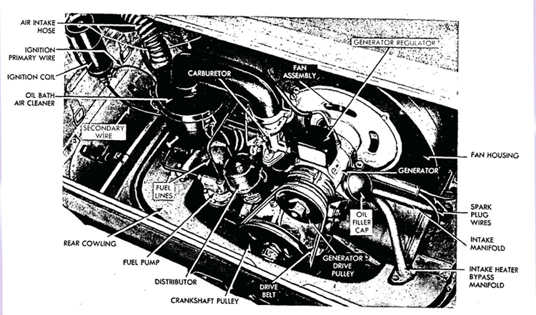
Figure 5—Engine Installed
conventional rocker arms and pushrods. An engine oil strainer is located in the bottom of the crankcase, and an oil cooler is mounted in the blower housing. Maximum economy of the engine is obtained by using a low grade of fuel. Tests prove that 80 octane fuel, diluted with 20 percent kerosene, offers smoothest carburetor operation and most economical engine operation.
b. Data / Metric System / U. S. System
Types: Four-cycle, horizontally
opposed, air-cooled
Number of cylinders / 4 / 4
Bore / 70-mm / 2-3/4 in.
Stroke / 64.29-mm / 2-17/32 in
AMA horsepower / 11.2 / 11.2
Piston displacement / 999.59 cc / 61 cu. in.
Compression ratio / 6.1 to 1 / 6.1 to 1
Firing order / 1-4-3-2 / 1-4-3-2
Ignition occurs / 5 degrees before top dead center / 5 degrees before top dead center
Suspension / Rubber, 3 point / Rubber, 3 point
Cylinders, cast in One piece, fins integral / One piece, fins integral
Pistons:
Material / Aluminum alloy / Aluminum alloy
Length / 70.64-mm /2-25/32 in.
Piston rings:
Type / 2 compression 1 oil control / 2 compression, 1 oil control
Width—compression / 3.17 mm 1/8 in.
Width—oil retaining /4.76 mm 3/16in.
Wristpin:
Type / Full floating / Full floating
Diameter / 19.84 mm / 25/32 in
Length 34.13 mm / 1-11/32 in
Retention / Snap rings / Snap rings
Valves:
Type / Poppet / Poppet
Location / In head / In head
Diameter of inlet port / 23.81 mm / 15/16 in
Diameter of exhaust port / 24.60 mm / 31/32 in
Inlet stem diameter /6.74 mm / 17/64 in.
Exhaust stem diameter /6.74 mm / 17/64 in
Inlet stem length 101.60 mm / 4 in.
Exhaust stem length 101.60 mm / 4 in.
c. Data / Metric System / U. S. Syltem
Valve seat insert:
Intake / Brass / Brass
Exhaust / Tool steel / Tool steel
Valve seat angle / 45 deg / 45 deg
Connecting rod:
Type / I-beam / I-beam
Length, center to center / 130.96 mm / 5-5/32 in
Connecting rod piston pin bushing:
Length / 19.84 mm / 2-5/32 in.
Material / Brass / Brass
Crankpin:
Diameter / 49.21 mm / 1-15/16 in
Length / 17.85 mm / 45/64 in
Valve lifter:
Type / Barrel / Barrel
Length / 63.50 mm / 2-1/2 in
Diameter / 15.87 mm / 5/8 in
Push rod:
Type / Tubular / Tubular
Length / 303.21 mm / 11-15/16 in
Diameter / 7.93 mm / 5/16 in
Crankshaft:
Material /Forged steel, heat treated / Forged steel, heat treated
Length 479.42 mm / 18-7/8 in
Crankshaft bearings:
Type Copper lead, steel backed shells / Copper lead, steel backed shells
Number of main bearings / 3 / 3
Diameter of bearings—front / 39.68 mm / 1-9/16 in
Diameter of bearings—center / 49.60 mm / 1-61/64 in
Diameter of bearings—rear / 49.60 mm / 1-61/64 in
Length of bearings—front / 20.63 mm / 13/16 in
Length of bearings—center / 17.85 mm / 45/64 in
Length of bearings—rear / 24.60 mm / 31/32 in
Camshaft:
Length / 342.90 mm / 13-1/2 in
Camshaft bearings:
Number / 3 / 3
Diameter / 23.81 mm / 15/16 in
Length / 25.40 mm / 1 in.
45. TUNE-UP.
a. Spark Plugs. Remove and clean spark plugs. Examine the plug
for cracked porcelain; adjust the gap with an 0.025-inch wire gage.
b. Battery and Ignition Cables. Inspect the ground strap and
cranking motor cable to see that connections are clean and tight and
free of corrosion; cover the connections with a thin layer of grease.
The battery is located in the left rear of the vehicle, forward of the
engine compartment. The cranking motor is mounted on the right hand side of the differential housing. Check' the primary ignition
system for clean and tight connections.
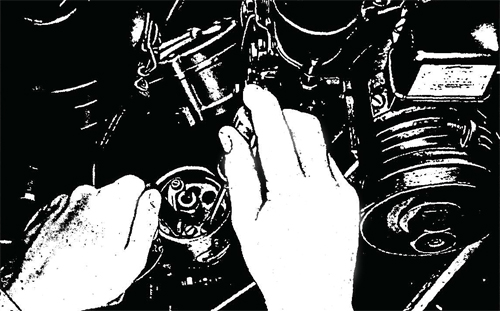
Figure 6—Adjusting Distributor Points
c. Distributor. Inspect distributor points for evidence of pitting
or burning. If not too badly pitted or burned, points may be filed
as a method of emergency repair. When points are badly pitted or
burned, replace. To adjust the contact points, turn the distributor
shaft until the fiber rubbing block of the breaker arm is exactly on
high point of the cam lobe. Adjust the gap between faces of adjustable point and contact arm point to 0.020-inch clearance by loosening the lock screw and turning the eccentric adjusting screw until
proper clearance is obtained. Tighten the adjustable point lock
screw and recheck the gap.
d. Carburetor (fig. 7). Remove and clean the oil-bath air cleaner and refill with clean oil to the proper level. Check the carburetor andgasoline line for leaks. No adjustment other than idling speed is provided. With engine warm, turn idler adjusting screw, out to enrich the mixture, in to lean the mixture.
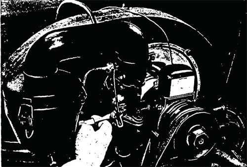
Figure 7—Adjusting Carburetor
e. Ignition Timing. Hand crank the engine until the No. 1 piston starts up on the compression stroke, and continue to crank the engine until the ignition timing dot on the crankshaft pulley is directly under the timing pointer on the crankcase. At this point, No. 1 piston is in firing position. Loosen the distributor hold-down bolt and rotate the distributor housing until the points open. Tighten the distributor hold-down bolt. Rotate the distributor clockwise to retard, or counter-clockwise to advance, the timing.
46. VALVE TAPPET ADJUSTMENT.
a. Hand crank the engine until No. 2 exhaust valve rocker is at highest position (exhaust valve fully closed). Loosen the tappet screw lock nuts on both tappet screws on No. 1 cylinder rocker arms and loosen the tappet screws. Insert an 0.008-inch feeler gage between the exhaust rocker arm and exhaust valve stem. Turn the tappet screw down until it holds the gage firmly. Then back off the screw until the gage can be pulled out with a light pull. Hold¬ing the screw accurately in this position, tighten the lock nut. Follow the same procedure for adjusting the intake valve tappet for No. 1 cylinder, using an 0.006-inch feeler gage.
Figure 8—Valve Mechanism Installed
b. Adjust the tappets for No. 4 cylinder by first closing the exhaust valve in No. 2 cylinder and then proceed the same as for cylinder No.
1. Thetappets are to be adjusted in the following sequence:
(1). Adjust No. 1 with No. 3 exhaust valve closed.
(2). Adjust No. 4 with No. 2 exhaust valve closed.
(3). Adjust No. 3 with No. 1 exhaust valve closed.
(4). Adjust No. 2 with No. 4 exhaust valve closed.
47. ROCKER ARMS.
d. Description. The rocker arm assemblies on the Volkswagen are located in the cylinder head. A metal cover protects the assembly from excess dirt and is held in place by a wire clip. The rocker arms are mounted on rocker arm shafts and are actuated by push rods. An adjusting screw and lock nut are provided in each rocker arm as a method of adjusting valve tappet clearance.
b. Removal (fig. 9). Remove the rocker arm cover by loosening the spring clip. Mark each rocker arm assembly and the cylinder head with the location of the arm so that the arms can be replaced in the same locations from which they were removed. Remove the two hex nuts and lock washers which hold the rocker arm shaft to
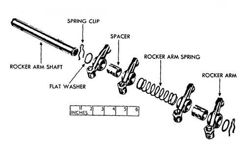
Figure 9—Rocker Arm Assembly Disassembled
the mounting studs and lift out the rocker arm assembly. A spring clip on each end of the shaft secures the component parts of the assembly to the shaft. With either spring clip removed, the two flat washers, two spacers, rocker arm spring, and four rocker arms can be removed from the shaft (fig. 9).
c. Installation. Assemble the component parts of the rocker arm assembly on the rocker arm shaft (fig. 9). Install the shaft on the two mounting studs provided and secure with two lock washers and hex nuts. Make certain that the rocker arms are installed in the same location from which they were removed. Adjust the tappets (par. 46). Install the dust cover over the valve mechanism and secure with the clip provided.
48. INTAKE MANIFOLDS.
a. Description (fig. 5). The intake manifold and heater bypass manifold are welded together below the carburetor connection
and are mounted above the engine. The intake manifold is connected
to the cylinder heads on each side of the engine. The heater bypass
manifold connects to the exhaust pipe brackets at the rear of the
engine and permits exhaust gases to circulate around the intake connection at the carburetor to assist in the vaporization of the fuel
mixture as it passes through the intake manifold to the cylinders.
b. Removal. Remove the generator drive belt, the generator,
fan, and fan housing assembly, the distributor to coil wires, the spark
plug wires, the oil-bath air cleaner, and disconnect fuel lines (par. 51). Remove carburetor (par. 62). Remove the two hex nuts and lock washers which secure the intake manifold to the mounting studs on each side of the engine. Remove the two cap screws and lock washers which secure the heater bypass manifold to the exhaust pipe brackets on each side of the engine, and remove the two manifolds as one unit.
c. Installation. Install the intake manifold and heater bypass manifold as a unit to the mounts on each side of the engine. Secure the intake manifold on each side with two lock washers. and hex nuts. Secure the heater bypass manifold on each side with two lock washers and cap screws. Install the carburetor (par. 62). Install the spark plug wires, the distributor to coil wires, connect the fuel lines, install the oil bath air cleaner, the generator, fan, and fan housing assembly, and the generator drive belt (par. 52).
49. EXHAUST MANIFOLDS.
a. Description (fig. 33). The exhaust system consists of two connected sections; one is a muffler and tail pipe mounted at the exhaust
port in front of the engine on each side, and the other is a solid pipe
running to the heater bypass manifold mounted at the rear of the
engine on each side. It is also supported by two brackets attached
to the underside of the engine. The two sections are joined together
by a C-clamp.
b. Removal. Remove the protection pan (par. 51). Remove the
two hex nuts and lock washers from the exhaust pipe at the front of
the engine. Loosen the two hex nuts on the support brackets under
the engine. Loosen the C-clamp nut holding the two sections of the
exhaust system together, and pull out the muffler and tail pipe section.
Remove the two hex nuts and lock washers at the engine rear mount
and pull out the solid pipe section of the exhaust system. The same
procedure must be followed to remove the muffler and exhaust pipe
on the opposite side of the engine.
c. Installation. Install a new gasket on the engine rear mount
and install the solid pipe section of the exhaust system onto the mount
and secure with two lock washers and hex nuts. Tighten the hex nuts
on the support bracket under the engine which supports the solid pipe
section. Slide the muffler and tail pipe section into position, entering
the tail pipe fitting into the solid pipe rear section. Tighten the hex
nut on the C-clamp connecting the two sections. Install a new gasket
on the engine front exhaust port. The muffler fits onto two studs at
the engine front exhaust port and is secured by two lock washers and
hex nuts. Tighten the hex nut on the support bracket under the engine which supports the muffler and tail pipe section of the exhaust
system. The same installation procedure must be followed to install
the remaining exhaust system on the opposite side of the engine.
Install the protection pan (par. 52).
Section XII. ENGINE, REMOVAL AND INSTALLATION
50. DESCRIPTION.
a. The Volkswagen engine is a four-cylinder, horizontally-opposed piston, air-cooled type. It is located at the rear of the vehicle and is mounted on the rear of the transmission. The generator, fuel pump, carburetor, distributor, and cooling fan assembly are mounted on the engine. The generator driven fan is located within a housing at the
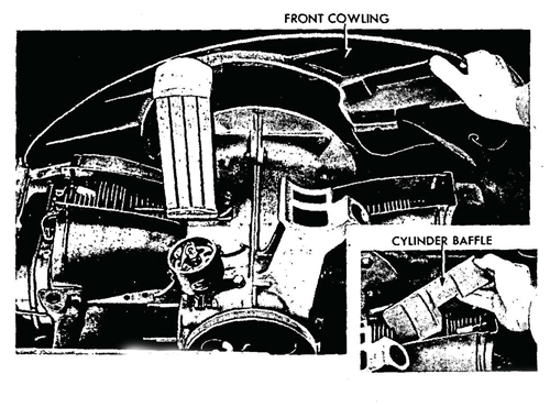
Figure 10—Removing Cylinder Baffle and Front Cowling
front of the engine and blows air through a baffle arrangement around the cylinders. The oil cooler is also mounted within this housing and is cooled by the fan. The distributor is driven off the crankshaft and the fuel pump is actuated by a cam on the distributor shaft. A gear type oil pump is located at the lower rear of the engine, forward of the crankshaft pulley.
51. ENGINE REMOVAL.
a. General. The Volkswagen engine is removed by lowering it to a dolly or other type of support.
b. Disconnect battery cable from cranking motor.
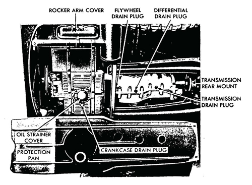
Figure 11—Rear Protect/on Pan Removed
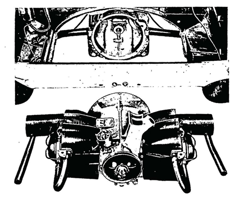
Figure 12—Engine Removed
c. Shut off the fuel supply by turning the fuel cock under the
fuel tank in a clockwise direction. Disconnect the gasoline pipe (tank
to fuel pump) at the fuel pump.
d. Remove the oil-bath air cleaner by loosening the C-clamp connection at the carburetor and by withdrawing the air intake rubber
hose from the port hole in the left wall of the engine compartment
(fig. 5).
e. Disconnect the choke and throttle cables at the carburetor.
f. Remove Generator. Remove the retainer nut which holds the
generator drive pulley to generator, and remove the pulley and belt.
Disconnect the two wires at the regulator. Loosen the C-clamp connection in front of the generator regulator and slide the clamp toward the fan housing. Remove the screw at each end of the fan
housing which fastens the housing to the engine. In lifting this assembly clear, tilt the left side upward to avoid the oil cooler mounted
within the fan housing.
g. Remove cowling at the front of the engine compartment by
removing the metal screw at each end which secures the cowling
at the base of the compartment (fig. 10).
h. Disconnect low and high tension wires at distributor.
i. Remove four bolts which hold the front protection pan to the floor and remove .the pan (fig. 11).
j. Remove two bolts which hold cranking motor to housing, and remove cranking motor.
k. Remove Engine. Two bolts and two studs hold the engine cylinder block to the flywheel housing. The upper right bolt was removed when the cranking motor was removed. Remove the upper left bolt, and remove nuts from the two lower studs. Pull the engine toward the rear of the vehicle until it is free of the clutch shaft, and lower it to the floor. Be careful to support the engine as it is being moved toward the rear of the vehicle so its weight will not be sup¬ported by the clutch shaft (fig. 12).
52. ENGINE INSTALLATION.
a. Raise the engine in position, supporting the weight as the
clutch shaft is entered through the clutch disk hub. Install the upper
left bolt to flywheel housing, and install two stud nuts.
b. Install cranking motor to flywheel housing by installing two retaining bolts.
c. Install front protection pan by installing four retaining bolts.
d. Connect high and low tension wires to distributor.
c. Place front cowling in position and install metal screw at each end.
f. Install Generator. Work the left end of the fan housing in
position over the oil cooler and lower the generator to its mounting
bracket. Install and tighten the C-clamp.. Connect generator regulator
wires. Place the fan belt on the generator drive pulley and place the
pulley on the generator shaft. Install nut which holds pulley to shaft.
g. Insert the air cleaner intake hose through the hole in the left
side of the engine compartment, and install the air cleaner on the
carburetor.
h. Connect gasoline line to fuel pump, and open fuel tank shut-off cock.
i. Connect cable to cranking motor.
j. Connect choke and throttle controls to carburetor.
53. DESCRIPTION AND TABULATED DATA.
a. Description. The clutch is a single plate, dry disk type, and is installed in the engine flywheel. A bell-shaped housing, extending from the differential housing, covering both clutch and flywheel, bolts to the engine rear plate. The clutch release mechanism is incorporated
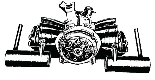
Figure 13—Clutch Assembly Installed
in the clutch housing. No adjustment for wear is provided other than adjustment of the clutch pedal linkage.
1). Tabulated Data.
Type / Single plate, dry disk
Free pedal travel / 3/4 in.
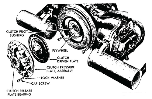
Figure 14—Clutch Assembly Removed
54. CLUTCH PILOT BUSHING.
a. Description. The clutch pilot bushing is a brass bushing
located in the flywheel retainer nut, and supports the transmission
main drive shaft (fig. 14).
b. Removal. To remove the bushing, first remove the engine
as outlined in paragraph 51. Remove the cap screws which secure
the clutch pressure plate assembly to the engine flywheel (fig. 14),
and remove the clutch assembly. The bushing and retainer nut can
then be screwed out of the crankshaft. The bushing can be pressed
out of the retainer nut.
c. Installation. Press new clutch pilot bushing into the flywheel
retainer nut. Screw retainer nut into crankshaft. Install clutch driven
plate in flywheel and install cap screws and pressure plate to flywheel. Install engine (par. 52).
55. CLUTCH RELEASE BEARING.
a. Description (fig. 15). The clutch release bearing is a carbon graphite bearing and is retained to the clutch bearing shaft by spring clips.
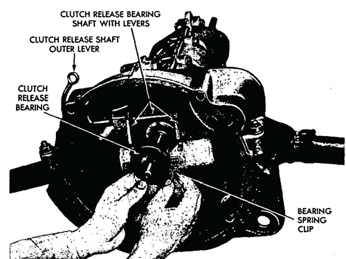
Figure 15—Clutch Release Searing Removal
b. Removal. Remove the engine (par. 51). Remove clutch (par.
54). Remove the spring clips which hold the bearing and retainer to
the clutch release bearing shaft levers (fig. 15).
c. Installation. Place clutch release bearing and retainer in the
grooves provided on the clutch release bearing shaft levers and secure
them in place with two spring clips. Install clutch (par. 54). Install
the engine (par. 52).
56. CLUTCH CONTROLS AND LINKAGE.
a. Description. Clutch operation is accomplished by a foot pedal
located in the extreme forward end of the driver's compartment on
the left side. The.foot pedal operates an arm on the pedal shaft. A
cable with clevises on each end connects the pedal shaft arm to the
clutch release operating shaft lever.
b. Adjustment of Clutch Control Linkage. To make certain that the clutch releases, and engages, completely, it must have atleast %-inch free pedal travel before the clutch starts to disengage. This clearance is maintained by adjustment of control linkage which connects the clutch pedal to the clutch release shaft lever. To obtain the correct adjustment, turn the nut on the clutch arm end of the cable in a clockwise direction until free travel in the clutch pedal is 3A inch, measured at the pedal pad.
c. Removal. Remove front protection pan. Remove protection
plate from front of brake junction arm by removing two metal screws.
Disconnect the brake cables from brake junction arm and pull out
arm. Pull out the service brake linkage rod. Remove clutch shaft support bracket from clutch shaft; it is secured by two cap screws. Remove clutch pedal by driving out the pin which holds it to the shaft.
Turn the clutch control shaft clockwise until the clutch cable is loose.
Remove the cable adjusting nut on the clutch arm end of cable and
pull cable to the front, and out. NOTE: The clutch cable passes
through a tube welded to the inside oi the tunnel housing.
d. Installation. Insert the clutch cable into the tube at the
rear entrance to the tunnel housing and secure the cable, adjusting
nut to the clutch release shaft outer lever. Turn the clutch control
shaft until the hook is in position to receive the other end of the
clutch cable. Reach through the tunnel housing from the front of
the vehicle with rod or stick and push the cable down over the clutch
control shaft hook. Turn the shaft counterclockwise to draw the
clutch cable tight. Install the clutch pedal to the clutch control shaft
and secure it with a lock pin. Install the clutch shaft support bracket
to the clutch shaft and secure with two cap screws. Install the service
brake linkage rod through the front entrance of the tunnel housing.
Install the junction arm in the same manner and install the service
brake linkage rod into the groove of the junction arm. Connect the
brake cables to the anchors on the front of the junction arm. Install
the protection plate over the front of the junction arm and secure
with two metal screws. Install front protection pan and secure with
eight cap screws.
57. CLUTCH DRIVEN PLATE.
a. Description. The single clutch driven plate is mounted on the transmission main drive shaft between the engine flywheel and the clutch pressure plate assembly (fig. 14).
b. Removal. Remove the engine (par. 51). Remove five cap screws which hold clutch pressure plate to flywheel and remove the clutch pressure plate. Lift the clutch driven plate out of the flywheel.
c. Installation. Install the clutch driven plate against the flywheel. Install the clutch pressure plate in the flywheel, and install five cap screws and lock washers which retain the pressure plate to the flywheel. Install the engine in the vehicle (par. 52).
Section XIV. ENGINE LUBRICATION SYSTEM
58. DESCRIPTION.
a. The engine is pressure lubricated by an oil pump driven from the front end of the camshaft The oil passes from a screen in the sump through the pump to the oil cooler. Oil from the cooler is
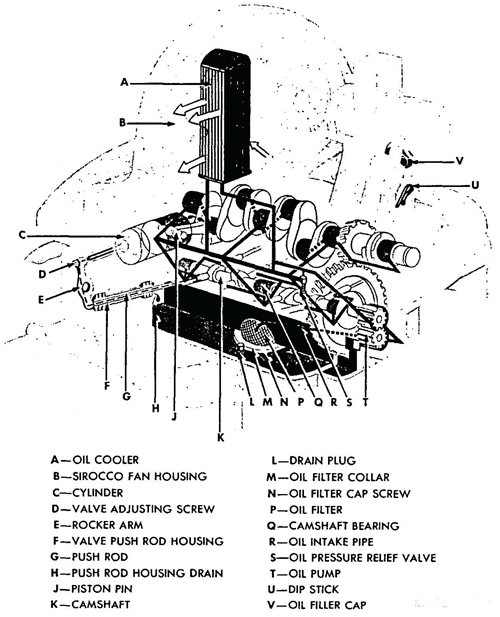
Figure 16—Engine Lubrication Diagram
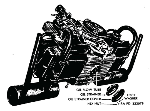
Figure 17—Engine Oil Strainer Removed
diverted through the camshaft to lubricate the camshaft bearings; oil from the cooler is also diverted to the crankshaft to lubricate the main bearings and connecting rod bearings. Oil is also directed, under pressure, through the valve lifter and push rod to lubricate the valve rocker arms.
59. OIL STRAINER ASSEMBLY.
a. Description. The oil strainer assembly is built into the bottom
of the engine crankcase and consists of a strainer, cover plate, two.
gaskets, six nuts, and six lock washers (fig. 17). The oil strainer is
shaped like an inverted cup with an open end cylindrical depression
in the center to accommodate the oil flow tube. Oil is drawn through
this oil flow tube by the pump, and is distributed throughout the
engine (par. 58). The engine does not have the conventional oil
pan, but the bottom of the crankcase is finned for oil cooling
purposes. The oil strainer assembly is mounted to six studs by lock
washers and hex nuts and may be easily removed for cleaning.
b. Removal. Remove the rear protection pan (par. 51). Remove
the six nuts and lock washers from the oil strainer coverplate studs
and remove the plate, strainer and gaskets from the mounting studs
(fig. 17).
c. Installation. Install a new gasket over the mounting studs on the bottom of the crankcase. Install the oil strainer over the mounting studs, allowing the oil flow tube to fit into the open end depression in the center of the strainer. Install a new gasket over the oil strainer. Install the coverplate on the mounting studs and secure with six lock washers and nuts. Install the rear protection pan (par. 52).
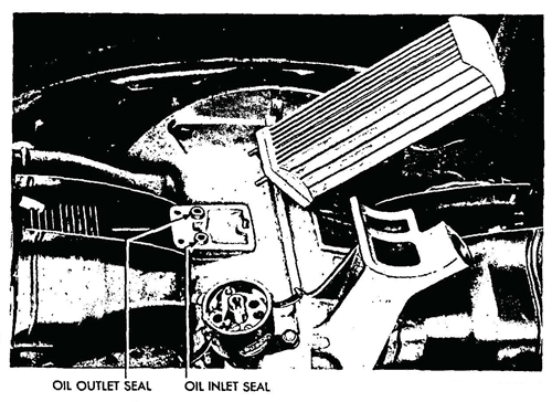
Figure 18—Oil Cooler Removed
60. OIL COOLER.
a. Description. The oil cooler consists of a series of vertical tubes
welded to a base and a cover. An inlet tube and an outlet tube con¬
nect at the base, allowing the circulation of Oil through the unit (fig.
18). The entire unit fits inside the fan housing and is mounted to the
block on the left side of the engine. It is secured to the engine by
three studs, lock washers, and nuts. Rubber seals or grommets at
the oil inlet and outlet ports insure the cooler against oil leaks.
b. Removal. Remove the generator drive belt, the generator,
fan and fan housing assembly, and the oil-bath air cleaner assembly,
as outlined in paragraph 47. Remove the left-hand baffle plate (fig.
10). Remove the nut and lock washer on the right-hand side of the
oil cooler which secures the oil cooler to the engine mounted stud.
Remove the two nuts and lock washers underneath the mounting
bracket on the left-hand side of the oil cooler which secure the oil
cooler mounted studs to the mounting bracket (fig. 18). Remove the oil cooler from the engine. Remove the two rubber oil seals from the oil inlet ports on the mounting bracket.
c. Installation. Install the two rubber oil seals into the oil inlet and oil outlet ports on the mounting bracket. Install the oil cooler onto the bracket, making certain that the oil seals fit into the ports on the bottom of the oil cooler. Secure1 the oil cooler to the bracket by a lock washer and nut on the engine stud on the right-hand side of the cooler, and by two lock washers and nuts on the two oil cooler studs underneath the mounting bracket on the left-hand side of the cooler. Install the left-hand baffle plate. Install the generator, fan and fan housing assembly, the oil-bath air cleaner, and the generator drive belt as outlined in paragraph 52.
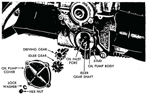
Figure 19—Oil Pump Disassembled
61. OIL PUMP.
a. The engine oil pump is driven by the front end of the cam¬shaft and is located below the crankshaft pulley. It is a gear-type pump.
h. Removal. The gears of the pump can be replaced without re¬moving the crankshaft pulley. Remove four nuts and lock washers which hold the oil pump cover to the crankcase, and remove the cover. Lift the upper gear (driving gear) from the oil pump body and then lift out the idler gear.
c. Installation. Place the idler gear on the idler gear shaft andinstall the driving gear. Be sure the tongue of the driving gear shaft enters the groove in the end of the camshaft. Install a new gasket over the cover studs and install the oil pump cover, lock washers, and nuts.
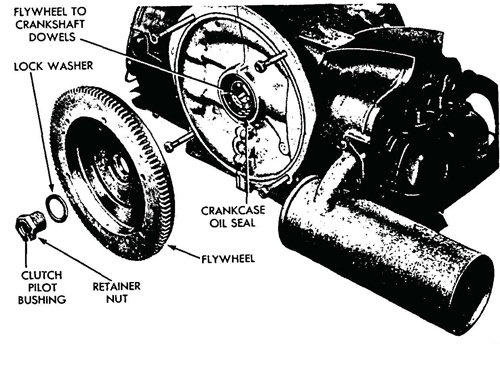
Figure 20—Flywheel Removed
62. OIL SEAL.
a. The crankcase rear oil seal is of rubber composition and must be inspected frequently to guard against oil loss through leakage.
b. Removal. Remove the clutch pilot bushing retainer nut and
lock washer and remove the flywheel from the crankshaft. Loosen the
three crankcase clamping bolts directly below the oil seal and one
clamping bolt on the top of the engine nearest the flywheel flange.
Carefully wedge a heavy screwdriver in the crankcase parting joint,
so as to spread the crankcase slightly. Pull the oil seal from its seat.
c. Installation. Place a new oil seal in the seat in the crankcase,
being sure it fits tightly against the seat flange. Remove the screwdriver from .he parting joint. Tighten the clamping bolt on the top
of the engine and the three bolts directly below the oil seal. Place
the flywheel on the studs of the crankshaft and install the lock
washer and clutch pilot bushing retainer nut. Tighten the retainer
nut securely.
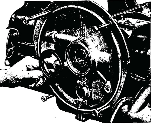
Figure 21—Removing Crankcase Oil Seal
Section XV. FUEL AND AIR INTAKE AND EXHAUST SYSTEMS
63. DESCRIPTION.
a. Fuel and Air Intake. Fuel for the Volkswagen is carried in an 8-gallon tank located under the right front cowling. The filler pipe for the tank projects through the cowling and is equipped with a snap-on cap. From the tank, fuel flows into a fuel strainer and sediment bowl mounted beneath the fuel tank; then is forced up through a wire mesh screen and into the flexible fuel line leading to the fuel pump, which is mounted on the engine. The fuel pump then forces the fuel into a fuel line to the carburetor which, in turn, introduces the fuel into the intake manifold. Air is drawn into the carburetor from a port in the left wall of the engine compartment. An oil-bath air cleaner removes dust from the air and conducts the air to the carburetor air intake.
1). Exhaust System. The exhaust system carries the burned gas from the engine to the atmosphere. The system consists of four exhaust manifolds (one for each cylinder), two mufflers, and four tail pipes.
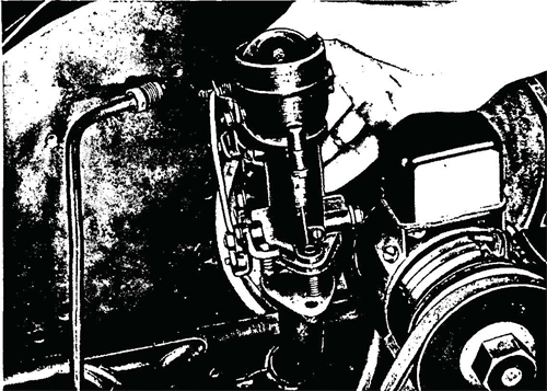
Figure 22—Carburetor Removal
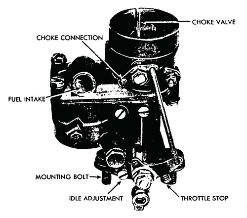
Figure 23—Carburetor Removed
64. CARBURETOR.
a. Description. The Volkswagen uses the downdraft type of carburetor. It is simple in design and, because its primary aim is economy of operation, no acceleration pump is used. The idle mix ture adjustment and the throttle stop screw are the only external adjustments provided (fig. 23).
b. Adjustment of Carburetor. After the engine has been warmed up to a normal operating temperature and is turning over about 500 revolutions per minute, turn the idle mixture adjustment (fig. 23) clockwise to its seat and back off the screw until smoothest idle performance is obtained.
c. Removal (fig. 22). Remove the oil-bath air cleaner (par. 66).
Remove the fuel line from the carburetor fuel intake. Remove the
choke and throttle connections. Remove the two hex nuts and lock
washers from the carburetor mount, and lift the carburetor up and
away from the intake manifold flange.
d. Installation. Install the carburetor on the flange of the intake manifold, and secure with two hex nuts and lock washers. Connect the choke and throttle rods on the carburetor. Install the fuelline from the fuel pump to the fuel intake port on the carburetor.
Install the oil-bath air cleaner (par. 66).
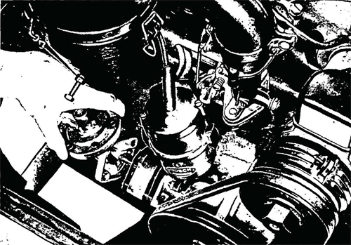
Figure 24—Fuel Pump Removal
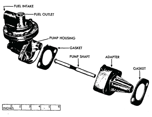
Figure 25—Fuel Pump and Adapter Disassembled
65. FUEL PUMP.
a. Description. The fuel pump is of the diaphragm type operating from a cam on the distributor shaft. It is mounted in the left
side of the engine crankcase below the distributor.
b. Removal. Disconnect the fuel inlet and fuel outlet lines from
the fuel pump. Remove the two nuts and lock washers from the
mounting studs at the base of the pump housing and remove the
pump, gaskets, and adapter (fig. 24).
c. Installation. Install new gaskets on each side of the adapter
and slide the adapter on the mounting studs. Install the pump shaft
through the adapter until it seats firmly against the cam on the distributor shaft. Install the pump housing on the shaft and firmly
against the adapter. Install and tighten two lock washers and nuts
which hold the pump to the mounting studs. Connect the fuel line
from the fuel tank to the intake port on the left of the pump housing
and connect the fuel line to the carburetor to the outlet port at the
top of the housing.
66. OIL BATH AIR CLEANER.
a. Description. The oil-bath air cleaner assembly consists of a wire mesh filter, a housing, an air intake rubber hose, and the car-
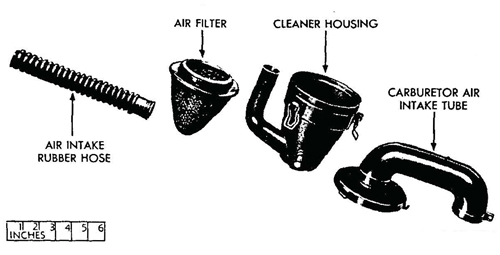
Figure 26—Oil Bath Air Cleaner Disassembled
buretor air intake tube (fig. 26). Sufficient oil in the housing at drain plug level assures efficient cleansing of the air on its way to the carburetor. The wire mesh filter should be cleaned, dipped in oil, and replaced at intervals as indicated in paragraph 19 d (1).
b. Removal. Pull out the air intake rubber hose from the porthole in the left wall of the. engine compartment and from the hous¬ing tube. Loosen the hex nut on the clamp which holds the carburetor air intake tube to the carburetor. Remove the oil-bath air cleaner assembly from the carburetor.
c. Installation. Install the oil-bath air cleaner assembly as a unit, securing it to the carburetor air intake tube by means of the clamp. Install the air intake rubber hose into the porthole in the left wall of the engine compartment and to the housing tube.
67. FUEL TANK.
a. Description. The fuel tank has a capacity of approximately eight gallons, and is located forward of the instrument panel underneath the cowling on the right-hand side of the vehicle. The fuel tank cap is the snap-on type. The fuel tank filler tube protrudes through the cowling.
b. Removal. Shut off the fuel supply by turning the fuel cock
underneath the tank in a clockwise direction. Disconnect the fuel line
at the fuel strainer. Remove the spare wheel from the top of the
cowling on the front of the vehicle. Remove the two bolts, nuts, and
washers which secure the tank to support brackets under the cowling. The fuel tank can then be lowered inside the vehicle. A support
should be placed under the tank to avoid damaging the fuel strainer.
c. Installation. Install the fuel tank into position underneath the cowling in front of the instrument panel on the right-hand sideof the vehicle. Place the steel band supports around the bottom of the tank and attach the ends to the cowl with two flat washers, nuts, and bolts. Install the spare wheel on the cowling top. Connect the fuel line, to the fuel strainer at the bottom of the tank. Open the fuel supply by turning the fuel cock underneath the tank in a counterclockwise direction.
68. FUEL LINES.
a. Description. Fuel is piped from the fuel tank to the carburetor by means of three sections of connected fuel line. The first
extends from the tank to the front end of the center tunnel housing.
It connects here with another line which passes through the tunnel
to the fuel pump on the engine. The third section extends from the
pump to the carburetor.
b. Removal. Unscrew the connectors at the carburetor and fuel
pump, at the front end of the tunnel housing,' and at the fuel tank.
The line through the tunnel housing is not fastened to it and can
be pulled out. Be careful not to kink the pipe during the removal
process.
c. Installation. Connect the fuel lines at the carburetor and
fuel pump, push line through tunnel to the connection in front, and
secure this line to the fuel line running to the fuel tank. Secure the
fuel line to the tank by screwing the connector snugly into the fitting.
Do not overtighten.
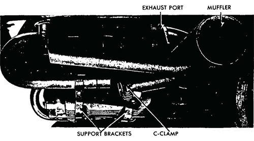
Figure 27—Muffler and Exhaust Manifold Assembly Removed
69. TAIL PIPES AND MUFFLERS.
a. Description. A muffler and two tail pipes on each underside of the engine connect to the four exhaust manifolds. The rear exhaust manifolds are a slip fit into the tail pipes leading to the mufflers. The forward exhaust manifolds are welded to the mufflers.
b. Removal (par. 49).
c. Installation (par. 49).
70. DESCRIPTION.
a. The engine is air cooled. Air is drawn into the engine principally through vents above the compartment lid, and is blown by a centrifugal fan through a baffle arrangement which directs the flow of air around the cylinders. The hot, used air is discharged through baffle exhaust ports at the rear base of the engine.
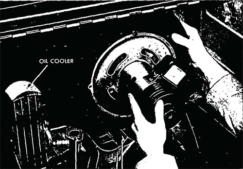
Figure 28—Removing Fan and Fan Housing With Generator Assembly
71. FAN AND FAN HOUSING.
a. Description. The fan, fan housing, and the generator comprise a unit structure. The centrifugal fan is mounted on the generator
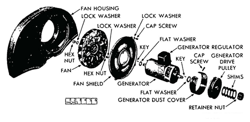
Figure 29—Fan Housing, Fan, and Generator Disassembled
armature shaft. The fan fits into a semicircular sheet metal housing which is mounted to the engine in a vertical position. The air is circulated within this housing, and is then blown around the cylinders. The fan housing also encloses the engine oil cooler which is mounted on the block to the left of the fan, air from the fan circulates through the oil cooler before entering the baffle arrangement at the base of the housing. The efficiency of the cooling system is further increased by finned cylinder heads, the base of the engine is also finned to aid in cooling the oil.
b. Removal (par. 51).
c. Installation (par. 52).
72. DESCRIPTION.
a. The ignition system consists of the battery, distributor, condenser, ignition coil, spark plugs, and the necessary high and low tension wires to complete the circuit for these units.
73. IGNITION COIL.
a. Description. The ignition coil is a standard, six-volt unit mounted to a bracket on the front of the fan housing.
b. Removal. Disconnect the ignition primary wire and the secondary wire (fig. 5). Remove the small wire running from the coil
to the ignition switch. Remove the two cap screws which secure theignition coil to the bracket on the front of the fan housing. NOTE:
Figure 5 illustrates an improvised mounting of the coil.
c. Installation. Install the ignition coil on the support bracket on the left front of the fan housing, and secure with two cap screws. Install the ignition switch wire to the coil terminal. Install the primary and the secondary wire to the coil terminals.
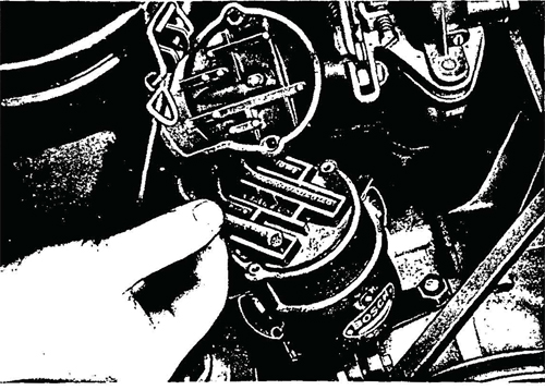
Figure 30—Removing Wires From Distributor Cap
74. DISTRIBUTOR.
a. Description. The distributor is an automatic advance type
with the condenser mounted externally. The timing can be advanced
or retarded by loosening the clamp screw and turning the distributor
body. The distributor wires are retained in the cap by a cover held
in place by two screws.
b. Removal (fig. 31). Unlatch the distributor cap retainer clips.
Move the cap, with secondary wires attached, to one side and out of
the way. Disconnect the primary wire from the terminal on the side
of the distributor. Remove the hex nut from the stud on the right-
hand side of the distributor which secures the distributor mounting
bracket to the engine block. Back off the nut on the mounting
bracket clamp bolt, and lift out the distributor.
c. Installation. Install the distributor in the engine block and
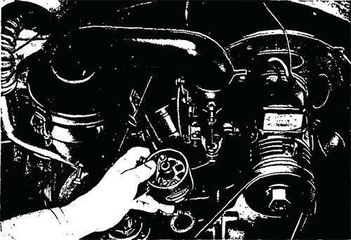
Figure 31—Distributor Removal
rotate the shaft until the tongue slips into the groove of the distrib¬utor drive connection. Tighten the nut on the mounting bracket clamp bolt. Install and tighten the nut on the engine mounted stud on the right-hand side of the distributor. Connect the primary wire to the terminal on the distributor. Install the distributor cap, and fasten retainer clips.
d. Condenser. The condenser is mounted externally to the base of the distributor housing. Remove the nut, lock washer, and flat washer which secure the condenser terminal, and remove the terminal (pig tail) from the distributor. Remove the screw and lock washer securing the condenser to the distributor, and remove the condenser. Clean the condenser and the area of the base plate under the condenser with emery cloth in order to establish the best possible ground. Install the condenser, securing with lock washer and screw. Connect the terminal (pig tail) to the distributor and fasten with flat washer, lock washer, and nut.
75. SPARK PLUGS.
a. Removal. Remove the spark plug wire. Before removing the spark plugs, blow all dirt and grit from spark plug recess and area surrounding the recess; otherwise foreign matter may enter the cylinder and cause damage. Use a spark plug socket wrench to remove the plugs and gaskets.
b. Installation. Check the gap between the electrodes and adjust to 0.025-inch if necessary. Install a new gasket on the threaded end of the plug. Use a spark plug socket wrench when tightening plugs to avoid damaging the porcelain. Install spark plug wire.
76. HIGH TENSION WIRING.
a. The distributor to coil wire and the spark plug wires are heavily insulated because of the high voltage load carried. If faulty wires are discovered, install new cables of the same length and quality.
Section XVIII. STARTING AND GENERATING SYSTEM
77. DESCRIPTION.
a. Starting System. The 6-volt starting system consists of the battery, battery cables and ground cables, the cranking motor sole¬noid, and the cranking motor. The starting system operates inde¬pendently of all other electrical equipment and wiring of the ve¬hicle. When the cranking motor button is depressed, it closes the circuit between the battery and the cranking motor solenoid.
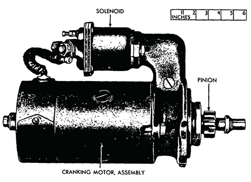
Figure 32—Cranking Motor and Cranking Motor Solenoid Installed
b. Generating System.
(1) The function of the generating system is to maintain a fully
charged battery under all normal operating conditions. The generating system consists of the generator, generator regulator, and ammeter warning light. The generator regulator controls the output of
the generator according to the requirements of the battery. The
ammeter warning light on the instrument panel should flash on under
the following conditions:
(a) When the ignition switch is turned on.
(b) When electrical equipment and lights are operating but
the motor is not running fast enough for the generator to overcome
the discharge from the battery.
(c) When electrical equipment is being operated with the engine not running.
(2) The generator regulator contains three units, each performing a distinct and independent function. These three units of the
regulator are known as the circuit breaker, the voltage regulator, and
the current regulator. It is mounted on the top of the generator
(fig. 33).
78. CRANKING MOTOR AND CRANKING MOTOR SOLENOID.
a. Cranking Motor.
(1) DESCRIPTION. The 6-volt cranking motor is secured to the
right-hand side of the transmission and differential housing. The
cranking motor is equipped with a sliding gear which meshes with
a ring gear on the flywheel to start the engine.
(2) REMOVAL. Remove the cranking motor as outlined in paragraph 51.
(3) INSTALLATION. Install the cranking motor as outlined in paragraph 52.
b. Cranking Motor Solenoid.
(1) DESCRIPTION. The cranking motor solenoid is mounted on
the cranking motor. The solenoid coil is energized when the crank
ing motor switch button on the instrument panel is pressed; the
plunger in the solenoid is pulled toward the rear, which moves the
outer end of the cranking motor clutch operating lever. The cranking motor pinion is moved into mesh with the teeth on the flywheel
to crank the engine.
(2) REMOVAL. Disconnect the wires from the cranking motor solenoid. Remove the pin and clevis from the solenoid link. Remove the cap screws and lock washers which hold the solenoid to the cranking motor, and remove it from its mount.
(3) INSTALLATION. Install the solenoid in position on the cranking motor, and secure with lock washers and cap screws. Install the pin and clevis in the solenoid link. Connect wires to solenoid terminals.
79. GENERATOR REGULATOR.
a. Description. The generator regulator consists of three entirely independent units encased in a sealed, moistureproof and dirtproof box mounted on the generator. These units are: the circuit breaker, which closes and opens the circuit between the generator and battery to prevent the current from flowing back through the generator when the engine is stopped; the current-limiting regulator, which controls the maximum output of the generator and prevents damage to the generator and battery; and the voltage regulator, which holds the electrical system voltage constant within close limits under the various operating conditions.
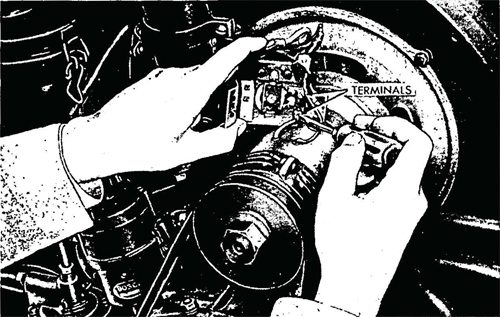
Figure 33—Removing Generator Regulator
b. Removal (fig. 33). Remove the two cap screws and lock washers which secure the generator regulator to the generator. Disconnect the wires from the terminals at the front and underneath the regulator, and remove the regulator from the generator.
c. Installation. Connect the wires to the terminals at the front
and underneath the regulator. Mount the regulator on the generator
over the holes provided for the mounting bracket and secure with
lock washers and cap screws.
80. GENERATOR.
a. Description. The generator is a 6-volt, two-brush unit mounted on top of the engine. It is driven by a V-type belt from the crank shaft. The output of the generator is controlled by the regulator which is mounted on top of the generator (par. 79).
b. Removal. The generator is attached at the front to the fan
and fan housing assembly and these three components are removed
as a unit as outlined in paragraph 51.
c. Installation. Install the generator as outlined in paragraph 52.
Section XIX. BATTERY AND LIGHTING SYSTEMS
81. DESCRIPTION.
a. The battery and lighting system in the Volkswagen is a 6-volt system including the battery headlights, blackout driving light, blackout taillight and service stop light, blackout taillight and blackout stop light, horn, and fuse boxes.
82. BATTERY.
a. Description. The battery is a 6-volt unit with a capacity of
75 ampere-hours. It is located under the rear seat on the left-hand
side of the vehicle.
b. Servicing Battery. The specific gravity of the battery electrolyte should be checked weekly by testing with a hydrometer. If the
specific gravity of the battery fluid is 1.250 or higher, only the level
of the water in the cells need be checked and distilled water added if
necessary. If the specific gravity is below 1.150, replace with a new
or fully charged battery, and return equipment battery to be placed
on charge. Keep the terminals and posts clean and tight, and cover
with a thin coating of grease.
c. Removal. Lift out the rear seat. Loosen the battery cable
terminal clamp nuts. Loosen the clamps on the battery posts. Re¬
move both positive and negative battery cable terminals from the
battery posts. Remove the hold-down clamp frame nut at each end
of the battery, lift off the frame, and lift the battery out.
Installation. Place battery in frame under left side of rear seat. Spread a thin coating of grease over the battery posts and terminals to retard corrosion. Install hold-down clamp and tighten. Make sure that hold-down frame nuts are tightened only enough to prevent battery movement. Connect cables to terminals, and tighten terminal clamp bolts.
83. HEADLIGHTS.
a. Description. Two single-bulb headlight assemblies are secured
to the front fenders. Lenses are removable (to facilitate replacing the
bulb and cleaning the reflectors) by loosening the screw at the bottom of the molding and removing molding with the lens. The head¬
lights are the prefocused type, so the only adjustment is that of aiming the light. This can be done by loosening the fillister head screw
in the mount, and turning the light to the proper position.
b. Maintenance and Adjustments. Care should be taken in
dismantling and replacing lenses and lamps because of their fragility.
Lighting switches must be "OFF" while such equipment is being replaced, to protect against short circuits and blown fuses. The head¬
light wiring is disconnected at the back of the headlight by pulling
out a plug.
c. Removal. Disconnect the wires by pulling the plug from the
rear of the headlight housing. From under fender, remove headlight
nut and lock washer. Lift headlight from fender*
d. Installation. Place headlight in position on its bracket. From
under the fender, install the headlight lock washer and nut. Connect
the wires at the plug at the rear of the housing.
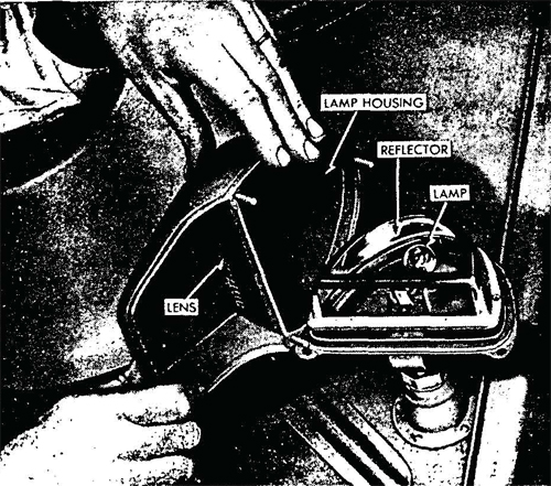
Figure 34—Blackout Driving Light Assembly
84. BLACKOUT DRIVING LIGHT ASSEMBLY.
a. Description. The blackout driving light assembly consists of, a base, housing, lens, reflector, and lamp (fig. 34).
b. RemovaL Loosen clsmp mrt on female socket and lift blackout driving light assembly out. To remove the housing from the base remove the nuts and lock washers from the three studs.
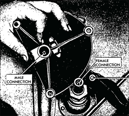
Figure 35—Blackout Driving Light Connection
c. Installation. Mount housing on light base and tighten at¬taching lock washers and nuts to studs. Install light assembly male plug into female socket and tighten clamp nut.
85. BLACKOUT TAIL AND SERVICE STOP LIGHT.
a. Description. A blackout tail and service stop light is at¬tached to the left rear of the vehicle on the frame crossmember. The blackout taillamp emits two small triangles of red light shielded from view except from the rear. The service stop light has an oval red lens (fig. 2).
b. Maintenance.
(1) REPLACE LAMP. Remove both door screws and lift door from body. Pull lamp unit from body. Insert new unit into body and push completely into socket. Place door in position on body and install both door screws.
c. Removal. Remove both plugs from, sockets behind lamp.
Remove the two stud nuts and lock washers which attach light to
frame. Lift light from frame.
d. Installation. Place light in position on frame and install two lock washers and stud nuts which attach light to frame. Insert wire plugs into sockets on rear of light. The plug with two wires goes to the top socket; the plug with one wire goes to bottom socket.
86. BLACKOUT TAIL AND BLACKOUT STOP LIGHT.
a. Description. The blackout tail and blackout stop lights are
attached on the right side of the rear crossmember of the frame. It
is similar to the blackout tail and service stop light described in the
preceding paragraph. The chief visual exception is that the stop light
emits only a small triangle of well-shielded light when the brakes
are applied.
b. Maintenance. Replace the lamp (par. 85).
c. Removal (par. 85).
d. Installation. Place light in position on frame and install the two lock washers and stud nuts which secure light to the frame. Install the wire plugs into the sockets on rear of the light. The plug with black wire goes to the top socket; the yellow wire to the bottom socket.
87. HORN.
a. Description. A vibrator type horn is mounted to the body immediately below the left direction signal indicator. A relay switch on the horn draws current directly from the ammeter to operate the horn.
b. Maintenance. Do not adjust the horn tone unless horn, has
been tampered with or damaged. When necessary, adjust as follows: Unscrew horn cover screw and lift cover from horn. Loosen the
adjusting nut lock nut. Screw the adjusting nut up or down until the
desired pitch is obtained. Hold the adjusting nut to keep it from
turning, and tighten the lock nut. Place the cover in position on horn,
and install cover screw.
c. Removal. Disconnect wire from horn terminal. Remove the two nuts, lock washers, and bolts which attach horn to the bracket, and remove the horn.
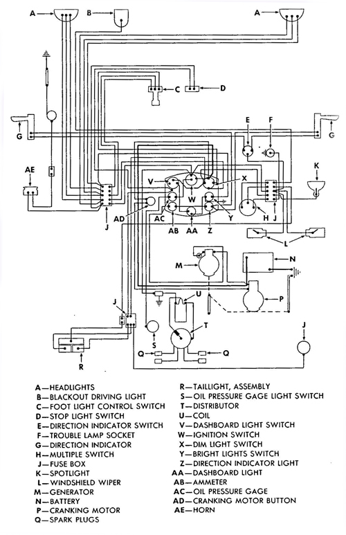
Figure 36—Wiring Diagram
1. Installation. Place the horn in position on the bracket and install the two bolts, lock washers, and nuts which attach horn to the bracket. Attach the horn wire to the horn terminal.
88. FUSE BOXES.
a. Description. Fuse boxes are found on the left- and right-hand sides of the instrument panel, and on the left-hand side of the engine housing. The use of the fuses is indicated in the wiring diagram (fig. 36), and on the diagram on the inside of the fuse box cover.
b. Removal. Remove wire connections from terminals and take out attaching nuts, lock washers, and screws. Remove the fuse box from panel and check all clips for tightness.
c. Installation. Mount the fuse box in position on the bracket and install attaching screws, lock washers, and nuts. Install wire connections at the terminals. Make sure no fuses are blown, and that they fit securely in the retaining clips.
Section XX. TRANSMISSION AND DIFFERENTIAL
89. DESCRIPTION.
a. Transmission. The transmission and differential comprise a unit structure enclosed in a housing of cast aluminum secured to the frame at three points; the front power train mount and the trans¬mission and differential support arms. The transmission offers four forward speeds and a reverse. The fourth gear is designed for high speed. The gear change rod links the transmission to the gearshift lever at the right of the driver's seat; it passes through the center tunnel and activates the gears. The transmission speeds and the respective gear ratio are as follows:
Transmission / Speed Ratio
First / 3.60-1
Second / 2.06-1
Third / 1.25-1
Fourth / 0.80-1
Reverse / 6.6 — 1
From the above, it will be noted that there is no direct drive which is commonly used in American vehicles. This factor has been sacrificed in order to obtain compactness of design within the transmission and differential. Power is transmitted from the engine crankshaft to the flywheel, through the clutch to the transmission main drive shaft, which is splined to the clutch driven plate, and to the transmission driven shaft. A small pinion, called the rear axle driving gear, connects the transmission driven shaft to the large ring gear in the differential. This large ring gear turns the drive shafts which are connected to the final drive assembly in the rear wheels.
b. Differential. The differential and transmission comprise a unit structure. The differential is a positive locking type. It consists of opposed plates having a circle of indentations resembling small cams. One plate has nine of these cams and the other eight. Attached to the differential ring gear is a round plate with a series of holes in which small pawls, with rounded ends, slide back and forth in the irregular path provided by the above mentioned cams. This operation offers a differential action at slow speeds. However, if one plate carrying the cams begins to turn much faster than the other plate, which would happen in the event that one wheel was in mud while the other remained on dry ground, excessive friction would cause the pawls and the cams to lock, thereby transmitting torque equally to the two driving wheels.
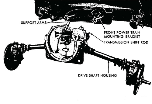
Figure 37—Transmission and Differential Removal
90. REMOVAL AND INSTALLATION.
a. Removal. The transmission and differential are removed as a unit. The engine must be removed as outlined in paragraph 51. Remove the two rear wheels (par. 103). Remove the two rear brake control cables and the clutch cable (par. 102). The drive shaft housing assembly must be removed from the rear torque arm; a split bracket on the drive shaft housing fits into a groove on the rear torque arm and is secured by three bolts, lock washers, and hex nuts. The inboard section of this split bracket is held tight to the drive shaft housing by two bolts, lock washers, and hex nuts, and these hex nuts must be backed off to allow this bracket to slide inward, relieving the tension on the rear torque arm in order that it may be withdrawn from the bracket. Remove the rear shock absorbers (par. 113). The transmission shift rod must be disconnected from the gearshift rod at the universal joint (fig. 39) at the top rear of the tunnel inside the vehicle: Remove the rear set screw with a socket head wrench. The differential and transmission support arms (fig. 37) fasten to the bell housing support (fig. 38) and are secured by two cap screws; these two cap screws must be removed. Remove two bolts, hex nuts, and lock washers from the front power train mount, withdraw the transmission and differential housing to the rear until the trans¬mission shift rod is clear of the front power train mount, and then lower.
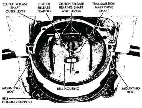
Figure 38—Bell Housing Support Removal
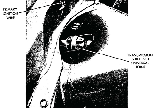
Figure 39—Transmission Shift Rod Universal joint
1>. Installation. Raise the transmission and differential housing into position between the support arms, and insert the transmission shift rod into the front power train mount and aline properly with the gearshift rod at the universal joint on top the tunnel, inside and at the rear of the vehicle (fig. 39). Secure the transmission and differential housing to the support arms with two cap screws. Secure the housing at the front power train mount with two bolts, lock washers, and nuts. Install a set screw into the universal joint (fig. 39), securing the transmission shift rod to the gearshift rod. Fit the split bracket on the end of the drive shaft housing to the torque rod arm and install three bolts, lock washers, and hex nuts. Tighten the inboard section of this split bracket at the clamp con¬nection, which prevents it sliding on the drive shaft housing. These last two steps must be carried out on both sides of the vehicle at the torque rod arms. Install the two rear wheels (par. 103). Install the two rear brake control cables and the clutch cable (par. 102). Install the engine as outlined in paragraph. 52.
91. REAR SUSPENSION.
a. Torsion bar suspension is employed for support of the rear axle housing and rear wheels. The system consists of a torque rocji^ enclosed within a housing mounted transversely to the floor of the.-vehicle. The torque rod is splined at each end to accommodate the splined sections of the torque arms. The upper end of each torque
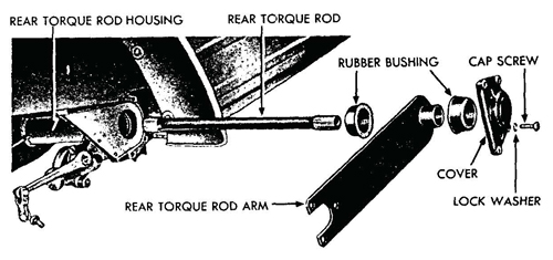
Figure 40—Rear Torque Rod Assembly
Disassembled arm fits on the splines of the torque rod, while the lower end of each torque arm attaches to the bracket near the outer end of each drive shaft housing (fig. 42). This forms a support for the rear wheel through the drive shaft housing, and permits each rear wheel to be suspended independently of the other.
92. FINAL REDUCTION ASSEMBLY.
a. Description. The final reduction in gearing is made at the wheel hub. Two spur gears are in a common housing and have IS and 21 interlocking teeth, respectively. This gives a drive reduction of 1.4 to 1. The arrangement of the reduction gear has the effect of raising the rear axle drive shaft and, consequently, the ground clearance is greater. The rear axle is attached to the large driven gear in this reduction assembly (fig. 41).
I). Removal. Remove the rear wheel and drum (par. 103). Remove the rear brake assembly (par. 103). Remove the four socket head set screws from the reduction gear housing cover and remove the grease retainer, cover, and backing plate. Then remove the rubber seal and outer axle bearing. Remove the eight hex nuts and lock washers from the reduction gear housing studs and pull off
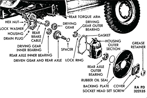
Figure 41—Final Reduction Gear Assembly
the outside section of the housing. Then remove in the following order: the housing gasket, driving gear outer bearing lock ring, driving gear outer bearing, rear axle outer bearing spacer, rear axle and driven gear, the driving gear, rear axle inner bearing, and the driving gear inner bearing. Loosen the two bolts which fasten the inside section of the housing to the drive shaft housing, and pull off the inside section of the housing. NOTE: Bearings are a light press fit, and can be removed easily by tapping lightly with a soft hammer. c. Installation. Install the following parts in the inside section of the reduction gear housing in the order given: the driving gear inner bearing, the rear axle inner bearing, the driving gear, the rear axle and driven gear, the rear axle outer bearing spacer, the driving gear outer bearing, the driving gear outer bearing lock ring; then install a new gasket and the outer section of housing. Secure the two sections of housing with eight lock washers and hex nuts on the housing studs. Install the rear axle outer bearing and the rubber oil seal. Install the backing plate, the reduction gear housing cover, and the grease retainer and secure with the four socket head set screws. Install the rear brake assembly (par. 103). Install the rear wheel and drum assembly (par. 102). The oil in the reduction gear assembly should be changed at the same time the transmission lubricant is removed. Drain the oil at the outlet plug (fig. 41) and pour in one-half pint of fresh oil. There is no need for a refill between oil changes because additional oil flows to these gears from the transmission via the duct in the drive shaft housing.
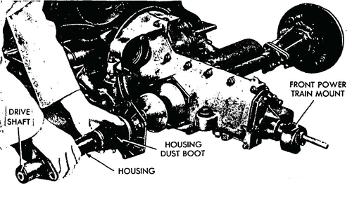
Figure 42—Drive Shaft Housing Removal
93. DRIVE SHAFT HOUSING ASSEMBLY.
a. Description. Two drive shafts, which transmit power from
the differential to the reduction gears, are enclosed in housings which
are attached to each side of the differential housing by a type of
universal joint and flange. The outer end of each drive shaft housing
•attaches to the reduction gear housing. A boot fastens to the inner flange of the drive shaft housing to keep out dust and dirt. The rear torque arm bracket is secured to the outer end of the drive shaft housing (fig. 41).
b. Removal. Remove the following assemblies: the rear wheel
assembly, the rear brake assembly, (par. 103) and the final reduction
assembly (par. 92). Remove the rear shock absorber (par. 113).
Remove the dust boot from the drive shaft housing. Remove the cap
screw and lock washer and five hex nuts and lock washers from the
hexagonal cover. Slide the drive shaft housing from the drive shaft
(fig. 42).
c. Installation. Slide the drive shaft housing onto the drive
shaft and attach the hexagonal cover to the differential housing
with a cap screw and lock washer and install five nuts and lock
washers on the mounting studs. Install the dust boot onto the cover
and housing joint. Connect the rear shock absorber (par. 113). Install the final reduction assembly (par. 92). Install the rear brake
assembly and the rear wheel assembly (par. 103).
94. DESCRIPTION.
a. The front axle consists of two rigidly attached tubes bolted to the body frame forward of the tunnel housing (fig. 44). The support arms are anchored within the axle tubes and are free to pivot. The torque arm pins attach to the support arm, and support the kingpin bearings. The front wheel spindles are affixed to the vertical kingpins which pivot freely. The front wheels are independently sprung on torque rods within the axle tubes. The torque rods are four individual lengths of band steel and stretch along the entire length of the axle tubes (fig. 43). A nut and set screw at the middle of each rod have been set to counteract twisting and side-to-side movements, and to allocate shock to each side of the suspension. Shock is transmitted from the support arms to the torque rods. Stops, with rubber buffers, prevent excessively violent springing action and the single acting, hydraulic shock absorbers dampen the return swing.
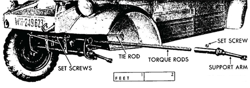
Figure 43—Front Suspension Torque Rods Removed
95. TORQUE RODS.
a. Description. The torque rods pass through the entire length
of the torque rod housings (axle tubes), and consist of two groups of
four steel bands each. They are anchored in the center to segregate
road shock to one side or the other. These rods twist as a unit, being
welded at their tips on each end. These welded ends farten to the
support arms which transmit road shock.
b. Removal. Remove the front wheel and drum assembly (par.
103). Remove the backing plate by cutting the wire to the three cap
screws and removing the cap screws and lock washers. Remove the
speedometer driven gear from the left front spindle by unscrewing
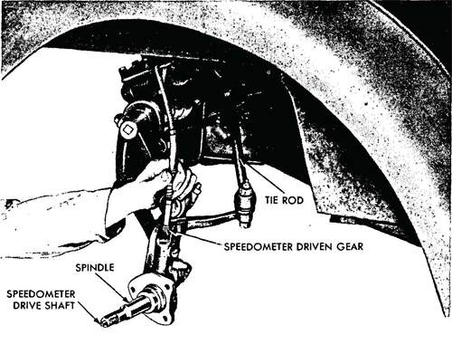
Figure 44—Left Front Spindle and Speedometer Driven Gear Removal
the adapter (fig. 44). Remove the spindle from the tie rod ball joint connection by taking off the castle nut and cotter pin. Remove the clamp nuts at the support arm connections, and remove the spindle. Loosen the set screws at the center and each end of the torque rod housing, and remove the support arm. Then pull the torque rods from the housing (fig.,43).
c. Installation. Install the torque rods into the housing. Install the support arm at the open end and secure the torque rods in the housing with three set screws, one at the center, and one at each end. Secure the spindle to the two support arms by tightening the clamp bolts. Install the spindle to the tie rod ball joint and tighten the castle nut; install a cotter pin through the castle nut. Install the speedometer driven gear into the left front spindle, and secure by tightening the adapter. Install the backing plate on the spindle and secure with three cap screws; install a new wire through the cap screws. Install the wheel and drum assembly (par. 103).
96. TORQUE RODS HOUSING ASSEMBLY.
a. Description. The front torque rods are housed in two rigidly attached tubes bolted to the body frame at the front end of the tunnel housing (fig. 45). These tubes are parallel, and are welded to four
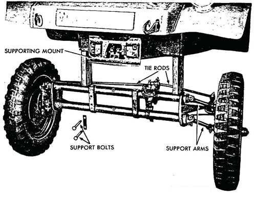
Figure 45—Front Suspension Removed
vertical crossmembers. The two center crossmembers are called frame heads. Lubrication fittings at each end of the housing tubes permit grease to reach the torque rods. Three socket head set screws, at the center and at the ends, anchor the torque rods within the housing tubes. The center anchor limits the twisting action of the torque rods to the right- and left-hand sides. The end anchors secure the torque rods to the support arms.
b. Removal. Support the front end of the body with blocks to
remove the front suspension (fig. 45). Remove the four bolts at the
frame heads; disconnect the steering gear assembly from the steering
column by loosening the clamp bolt and nut. Roll the front suspen
sion away from the body.
c. Installation. Mount the torque rods housing assembly to the
body frame and secure with four bolts, nuts, and lock washers through
the frame heads to the supporting mount at the front end of the
tunnel housing. Connect the steering gear assembly to the steering
column by tightening the clamp bolt and nut.
97. TIE ROD ASSEMBLIES.
a. Description. The right and left tie rods are fastened to the steering Pitman arm by means of ball and socket joints. These tierods transmit steering impulses from the gfryring ^esr assembly to the front wheels. At the front wheels, the tie rods fasten to the spindles by xneans of ball and socket joints.
b. Removal. Remove the ball stud nut and tap the tie rod from the Pitman arm or steering knuckle arm.
c. Installation. Place the tie rod in position and insert the ball
stud in the Pitman arm and steering knuckle arm. Install and tighten
the ball stud nut
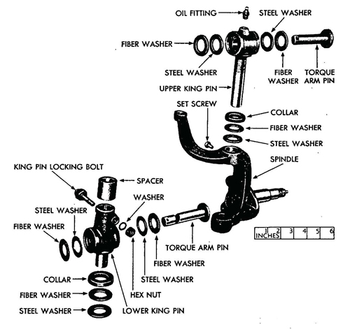
Figure 46—Lett Front Spindle Disassembled
98. SPINDLE ASSEMBLIES.
a. Description. The left and right spindles are the mounts for the front wheels and attach to the front suspension by means of support arms. The spindle arms connect the left and right tie rod assemblies. The left front spindle accommodates the speedometer driving and driven gears and the speedometer drive shaft which passes horizontally through the spindle and attaches to the grease cup by means of a cotter pin (figs. 44 and 47).
b. Removal. Remove the spindles (par. 95).
c. Installation. Install the spindles (par. 95).
99. SUPPORT ARM ASSEMBLIES.
a. Description. Two support arms on each end of the torque rod
housing assembly transmit springing action to the front wheels. The
support arm assembly consists of an arm and sleeve arrangement
welded together at approximately right angles. The sleeve fits into
the torque rod housing over the torque rods. A set screw anchors the
rods within the sleeve. The arm is the lever which runs from the
torque rods to the spindle and attaches to the spindle at the vertical
kingpin (fig. 43).
b. Removal. Remove the support arm assemblies (par. 95).
c. Installation. Install the support arm assemblies (par. 95).
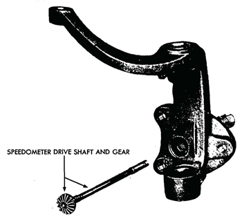
Figure 47—Speedometer Drive Gear 110
100. SPEEDOMETER DRIVE ASSEMBLY.
a. Description (figs. 44 and 47). The speedometer is driven by
the left front wheel. The speedometer drive assembly consists of a :
drive shaft, driving gear, and driven gear with an adapter. The drive
shaft passes horizontally through the spindle and attaches to the
grease cup by means of a cotter pin through the shaft. At the other
end of the drive shaft is the driving gear which meshes with the
driven gear within the spindle. The driven gear and shaft enter
the spindle from the top and are secured by an adapter which screws
into the spindle vertical cylinder. A metal drive plug at the gear end
of the drive shaft housing protects the gears from dirt and acts as
a lubricant retainer.
b. Removal. Remove the left front wheel and drum assembly
(par. 103). Remove the backing plate (par. 95). Remove the
speedometer driven gear (par. 95). Remove the spindle (par. 95)
and remove the vertical kingpin from the spindle. By tapping the
attaching end of the speedometer- drive shaft, the drive plug can be
forced out. Remove the speedometer drive shaft and gear from the
spindle.
c. Installation. Install the speedometer drive shaft and gear into
the spindle through the horizontal cylinder. Install the drive plug into
the opening. Install the vertical kingpin on the spindle and mount
the spindle on the vehicle (par. 95). Install the speedometer driven
gear (par. 95), the backing plate (par. 95), and the wheel and
drum assembly (par. 103).
Section XXIII. SERVICE AND PARKING BRAKES
101. DESCRIPTION.
a. The brakes on the Volkswagen are a mechanical, internal ex¬panding type. The foot pedal application and the hand lever application each work all four brakes. The brake cables anchor to a junction arm between the torque rods housing tubes at the front of the vehicle (fig. 48). When the foot brake pedal is depressed, it causes the control pedal shaft to turn, forcing the cable junction arm to move forward pulling the brake cables at the four wheels. The hand brake lever has the same effect, but it is not attached to the control pedal shaft. It is attached by means of a ratchet arrangement to the parking brake linkage rod running through the tunnel housing to the junction arm at the front (fig. 49).
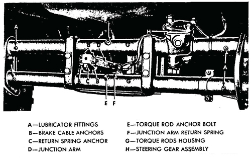
Figure 48—Brake Control Junction Arm
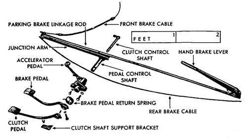
Figure 49—Control Pedals and Brake Linkage
102. CONTROLS AND LINKAGE.
a. Description (fig. 50). The accelerator pedal is welded to a
sleeve which mounts on the control pedal shaft. This shaft extends
out, and to the left, at right angles from the tunnel housing. The brake pedal is mounted directly to the control pedal shaft. The
clutch pedal fits onto a shaft which extends through the control
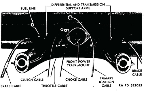
Figure 50—Control Cables
pedal shaft from the right-hand side. The clutch cable is attached to a hook on this shaft. When the clutch pedal is depressed, the shaft turns, pulling the cable which passes through the tunnel and connects, to the clutch release shaft outer lever.
b. Removal (fig. 49). Remove the protection pan at the front of
the vehicle and disconnect the brake cables at the junction arm
anchor (fig. 48). Disconnect the rear brake cables at the wheels
by removing the attaching bracket. Pull the rear brake cables out
through the rear of the tunnel housing. Remove the front brake
cables by removing the attaching brackets. Using a wooden stick or
any similar extension, reach into the front of the tunnel housing and
lift the clutch cable off the clutch control shaft hook. Remove the
pin which secures the clutch pedal, to the clutch control shaft, and
remove the pedal and shaft. Remove the cap screw and lock washer
which secures the brake pedal to the control pedal shaft, and remove the pedal. Release the brake pedal return spring. Remove the
accelerator pedal and mounting bracket by removing the cap screws
and lock washers. Remove the pin at the hand brake lever clevis,
and remove the lever. Pull the brake cable junction arm out through
the front of the tunnel housing. Pull the control pedal shaft out of
the tunnel housing from the right-hand side. Pull the parking brake
linkage rod out through the front of the housing.
c. Installation (figs. 49 and 50). Install the control pedal shaft through the housing, and install the junction arm through the front of the housing onto the control pedal shaft. Install the parking brake linkage rod through the front of the housing, yoke end first, and so it fits into the groove of-the. junction arm.; Connect the hand brake lever to the linkage rod, and secure with pin and cotter pin at the clevis. Install the accelerator pedal and bracket on the control pedal shaft, and secure with cap screws and lock washers. Install the brake pedal return spring and the brake pedal onto the control shaft, and fasten the spring to the' accelerator bracket and brake pedal. Secure the pedal with a lock washer and cap screw. Install the clutch pedal shaft through the control pedal shaft from right-hand side, and install clutch control on the shaft. Secure the clutch pedal with a straight pin through the shaft. Using a wooden stick or any similar extension, reach into the front of the tunnel housing and maneuver the clutch cable onto the clutch control shaft hook. Install the front brake cables at the junction arm and backing plate. Install the rear brake cables into the rear of the tunnel housing (fig. 50) and secure to the junction arm. Adjust the brakes as outlined in paragraph 103' and install the eight cap screws which hold the protection pan at the front of the vehicle.
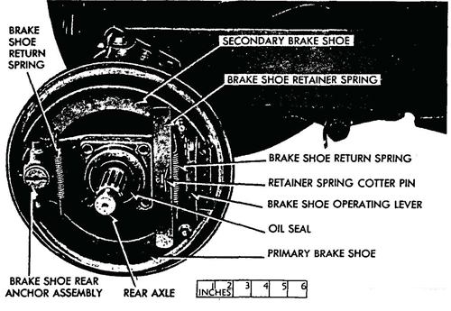
Figure 5I-—Brake Assembly Installed
103. SHOE ASSEMBLIES.
a. Description. The brake shoe assembly consists of the primary brake shoe, secondary brake shoe, two return springs, shoe retainer spring, two brake shoe anchors, and the brake shoe operating lever
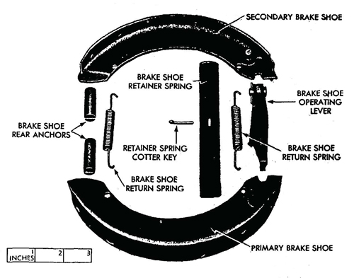
Figure 52—Brake Shoes Removed (fig. 51).
The shoes are secured to the backing plate by the rear anchor and by the retainer spring. The brake is adjusted at the anchors and at the cable which attaches to the operating lever. A toggle action at the lever expands the shoes against the brake drum as the cable is pulled.
b. Adjustment. A minor brake adjustment consists of tightening
the adjusting wedge bolt (fig. 53). Turn the adjusting wedge bolt
in one notch at a time until the desired brake action is obtained. If
proper adjustment of the shoes cannot be obtained by this method,
It indicates that the brake cable has stretched. Tightening the brake
cable clamping nut (fig. 54) will.shorten the cable and compensate
for slight cable stretch.
c. Removal. Remove the wheel, hub cap and lugs on the drum.
Remove the wheel. Remove drum assembly. On front wheels, remove two wheel nuts, two washers, outer bearing race, outer bearing
and brake drum. On rear wheels, remove cotter pin and nut, and then
loosen drum by a sharp hammer blow on the end of the axle. NOTE:
Use a piece of brass or copper to protect end of shaft. Disconnect
cable attaching plate at rear of backing plate. Remove cotter pin
from the retainer spring and remove the two return springs from
the shoes. Lift off the shoes, anchor pins, and operating lever (fig. 52).
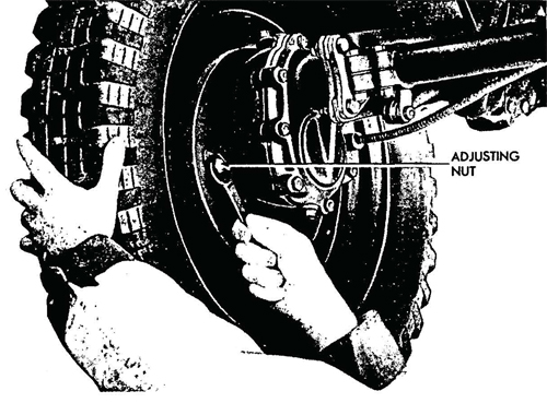
Figure 53—Adjusting Brake Shoes
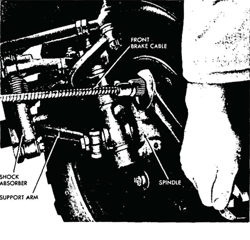
Figure 54—Adjusting Brake Cable 11
d. Installation. Install the anchor pins into the backing plate boss, and place the brake shoes in the grooves on the pins. Install rear return spring. Install the brake operating lever. Connect the brake cable to the brake shoe operating lever, and place the shoes into the grooves of the lever. Install front return spring. Install shoe retainer spring and secure with cotter pin (fig. 51). Install brake drum assembly on front wheel, after bearings have been coated with grease, replace inner bearing, brake drum, outer bearing, race, flat washer and nut. Pull nut up until tight and back off Vi turn, then check nut with lock washer and nut. Lock tightly without changing position of inside nut. Replace grease cap. On rear wheel, replace brake drum and secure tightly with nut and cotter pin. Install wheel. Adjust the brakes (step b above).
104. DESCRIPTION.
a. The steering gear is the worm and sector type, and differs from the conventional construction in that the steering worm shaft is short, and an extension is used to connect the worm shaft to the steering wheel. The sector shaft is fitted with a socket into which the sector bearing is located. The sector bearing is designed to mesh with the threads of the worm shaft. The sector shaft extends through the steering gear housing, and the steering Pitman arm attaches to the lower end of the sector shaft. The opposite end of the Pitman arm is designed to accommodate two ball studs which are located in the inner ends of the tie rods. The tie rod b^ti studs are attached to the Pitman arm, and the tie rods extend to" the steering knuckle arms. Ball studs in the outer ends of the tie rods are attached to the steering knuckle arms.
105. STEERING PITMAN ARM.
a. Description. The steering Pitman arm is located beneath
the steering gear assembly, and fastens to the sector shaft by a clamp
bolt, nut, and lock washer. The ball end of the steering Pitman arm
provides for two ball and socket joints to which are attached the
left and right tie rods. The conventional drag link is not used on this
vehicle.
b. Removal. Remove the protection pan from the front of the
vehicle by removing the eight cap screws which hold it in place.
Remove the clamp bolt, nut, and lock washer at the b se of the sector shaft, and slide the Pitman arm from the sector shaft Remove the two ball and socket joints from the other end of the steering Pitman arm.
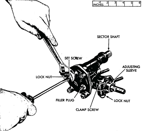
Figure 55—Adjusting Steering Gear
c. Installation. Install the steering Pitman arm to the sector shaft and secure with a clamp bolt, lock washer, and nut. Install two ball and socket joints on the other end of the arm, and install the left and right tie rods to the joints. Install the protection pan on the front of the vehicle, and install and tighten the eight cap screws.
106. STEERING GEAR ASSEMBLY.
a. Description. The steering gear assembly is mounted to the
upper torque rod housing at the front left center of the vehicle
(fig. 45).
b. Adjustment. There are two adjustments provided for the steering, one to eliminate backlash between the steering gear worm
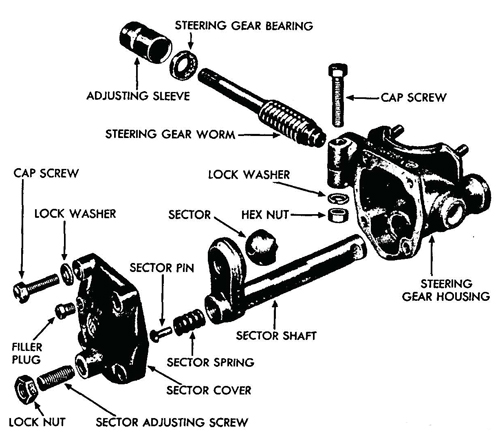
Figure 56—Steering Gear Disassembled
and its bearing, and the other to eliminate backlash between the steering gear worm and the sector. To eliminate backlash between the steering gear worm and bearings, turn the front wheels to the straight ahead position. Loosen the clamp screw at the top of the steering gear housing, and tighten the adjusting sleeve (fig. 56). Tighten the sleeve only enough to eliminate up-and-down motion of the steering gear worm, and tighten the housing clamp screw. To eliminate backlash between the steering gear worm and sector, turn the front wheels to the straight ahead position. Loosen the sector adjusting screw lock nut (fig. 56) and tighten the sector adjusting screw until no backlash exists between the sector and the steering gear worm. Tighten the adjusting screw lock nut.
c. Removal. Remove the protection pan on the front of the vehicle. Remove the steering Pitman arm (par. 105). Remove the clamp bolt and nut at the steering column connection, and separate the steering column from the steering gear assembly. Remove nuts and lock washers from mounting studs on the torque rod housing bracket, and remove the steering gear assembly.
d. Installation. Install'the steering gear assembly on the torque rod housing bracket, and secure lock washers and nuts to the mounting studs. Connect the steering column to the steering gear assembly, and tighten the clamp bolt, lock washer, and nut. Install the Pitman arm to the sector shaft (par. 105).
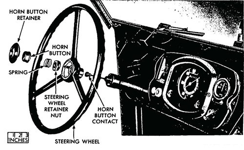
Figure 57—Steering Wheel Removed
107. STEERING WHEEL ASSEMBLY.
a. Description. The steering wheel is the standard type commonly used in American vehicles. The steering wheel assembly con¬
sists of the horn button retainer, horn button, spring, retainer nut,
wheel, and horn button contact.
b. Removal. Pry the horn button retainer from the hub of the
wheel. Lift out the horn button and spring, and remove the steering
wheel retainer nut. The wheel is splined to the steering column tube,
and care should be taken in order to keep from damaging the splines
when it is lifted off (fig. 57). Pull the steering wheel from the steering
tube.
c. Installation. Install the steering wheel on the splined steering
tube, allowing the horn button contact wire to fit through the wheel
hub. Tighten the retainer nut to draw the wheel onto the tube, and
install the spring and horn button. Secure the button with the tight-
fitting retainer which presses into position over the button.
Section XXV. TIRES. TUBES, AND WHEELS
108. DESCRIPTION.
a. The Volkswagen is equipped with five steel disk wheels with deep set rims, and low-pressure synthetic tires and tubes, size 5.25-16. Air pressure should be approximately 20 pounds in front tires and 26 pounds in the rear tires.
109. TIRES, TUBES, AND WHEELS.
a. Removal. Jack up the vehicle and pry the hub cap from the
wheel. Remove lug nuts and pull wheel and tire from drum. Remove
valve core from valve stem to deflate tire thoroughly. Pry the tire
from the rim, and pull the inner tube out of the tire.
b. Installation. Install tube in tire. Install tire and tube on wheel rim, using care to avoid pinching the tube. Inflate tire to proper pressure and install wheel on the drum, and secure with lug nuts; tighten the nuts gradually and alternate from side to side to ensure a proper fit. Lower vehicle to ground and withdraw the jack.
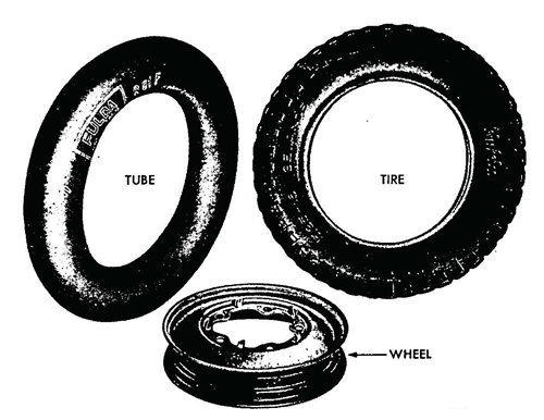
Figure 58—Wheel, Tire, and Tube
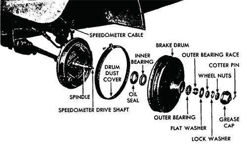
Figure 59—Left Front Brake Drum and Wheel Bearing Disassembled
110. ADJUSTMENT.
a. No provision is made for adjusting the caster or camber angles of the front wheels of the Volkswagen.
b. Toe-in can. be adjusted as follows: Place the front wheels in
a straight ahead position; measure the distance between the rear of
the front wheels and the front of the front wheels, being sure that
these measurements are taken at the same height from the ground
in each case. If the distance between the front of the front wheels is
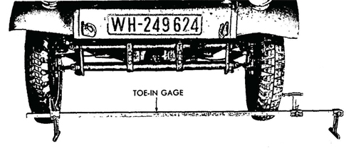
Figure 60—Front Wheel Toe-in Adjustment
VLG to Vs inch less than the distance between the rear of the front wheels, toe-in is correct. If this measurement is not obtained, loosen the tie rod yoke clamp bolt at each end of each tie rod. Turn each tie rod until each wheel points exactly straight ahead. Turn each tie rod enough to make each wheel toe-in %6 inch; this will give a combined toe-in of Va inch, which is satisfactory.
111. DESCRIPTION.
a. The Volkswagen is equipped with single-acting, hydraulic shock absorbers on the front suspension, and double-acting, hydraulic shock absorbers on the rear suspension. The base of the front shock absorber is bolted to the torque rdd housing support and the top to the upper support arm (fig. 61). The rear shock absorber is mounted to a bracket behind the rear torque rod housing, and to the rear torque arm bracket on the drive shaft housing.
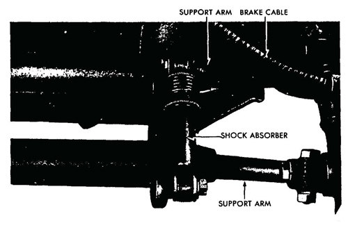
Figure 61—Front Shock Absorber Installed
112. FRONT SHOCK ABSORBERS.
a. Description. The front shock absorbers are single-acting, airplane-type; they cushion the return spring action of the front torque rods.
b. Removal (fig. 61). Remove cotter pin and castle nut at the base mount of the front shock absorber. Remove the cap screw and flat washer which secure the absorber to the top support arm. Re¬move the shock absorber from the mounts.
c Installation. Install the front shock absorber to the upper support arm and to the torque rods housing support. Be careful not to damage the.rubber bushings. Install flat washer and cap screw at top mount, and castle nut and cotter pin at base mount.
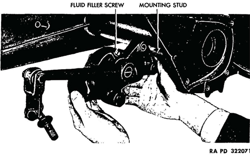
Figure 62—Removing Rear Shock Absorber
113. REAR SHOCK ABSORBERS.
a. Description. The rear shock absorbers are the double-acting,
hydraulic-type; they are mounted to a bracket directly behind the
rear torque rod housing and to the rear torque arm bracket on the
drive shaft housing. The fluid level can be checked at the filler opening, and should be maintained at the top of the opening.
b. Removal (fig. 62). Disconnect the link at the drive shaft
housing. Remove the hex nut, cap screw and lock washers from the
bracket mount behind the rear torque rod housing. Remove the nut
and flat washer from the rear torque arm bracket on the drive shaft
housing, and remove the shock absorber.
c. Installation (fig. 62). Install the rear shock absorber to the
stud on the mounting bracket, and. secure with a lock washer and
nut. Install a lock washer and cap screw to attach the shock absorber
to the torque rod housing. Connect the shock absorber link to the
drive shaft housing.
Section XXVII. INSTRUMENT PANEL AND INSTRUMENTS
114. DESCRIPTION.
a. The indicating instruments are carried in an instrument panel immediately below the windshield. The instruments indicate the condition of the various components of the vehicle while it is in motion.
115. REPLACEMENT.
a. Instrument Panel. The instrument panel is attached to the
body by a single bolt at each end of the panel. Remove these bolts
and disconnect instrument wires and cables from the instruments,
and remove the panel. When installing a new panel, first connect the
instrument wires and cables to the corresponding instruments. Place
the panel in position and install the bolt, nut, and lock washer which
secure each end of the panel to the body.
b. Instruments. Disconnect instrument wires or cables from
the instrument to be replaced. Remove the nuts and lock washers
from the studs which hold the instrument to the panel, and remove
the instrument. When installing a new instrument, see that it is
securely attached to the instrument panel before connecting the
wires or cables.
116. DESCRIPTION.
a. The base stamping comprising the floor of the vehicle is ribbed. The sheet steel center housing is tunnel-shaped and has a piece of sheet metal welded to the under side. It forks in the rear in order to form a mount for transmission and differential. In the front, the center tunnel broadens out and supports the front suspen¬sion assembly. This center tunnel houses the throttle, clutch, choke cables, the two rear brake cables, the parking brake linkage rod, the brake cable junction arm, the transmission shift rod' and the fuel line.
b. The all steel body has a space for equipment above the front and rear suspensions. The doors are hinge-bolted to the center posts and the fenders are welded to the body. The windshield is made of safety glass and can be lowered and secured in a horizontal position. Detachable curtains are provided for inclement weather conditions. The adjustable front seats are firmly bracketed to the undercarriage. The rear seat cushion is set into the carriage and the back of the seat opens into the accessory box.
c. A box for holding papers and a hand lamp is found in front on the left-hand side. Combat equipment for the crew is sometimes placed under the front seats and sometimes under the right-hand side of the rear seat. A spade is held in brackets on the right side of the front cowl.
117. BATTERY BOX.
a. The battery box is secured to the floor under the left rear seat by cap screws and lock washers. It is necessary to lift out the seat cushion to reach the battery box. Disconnect battery cables and lift out battery. Remove cap screws and lock washers from the flanges and lift out battery box. Install the battery box by securing cap screws and lock washers; install battery into box and attach cables, and install rear seat cushion.
118. WINDSHIELD WIPER BLADE.
a. When a new blade is necessary, install it on the end of the windshield wiper arm at the hook connection.
119. SEAT CUSHIONS.
a. The seat cushions are a loose fit and can be removed and installed freely.
120. DOORS.
a. The doors on each side of the vehicle fasten to the. center posts by two hinge bolts in a common hinge. They can be removed easily by driving out the bolts. Install by placing in position on the hinges and tapping bolt into place from the top of the hinge.
121. FLOOR GRATING.
a. The wooden floor grating is a loose fit. It is held in place by the front seat brackets. Remove the cap screws and lock washers from front seat brackets and lift out seats. Remove floor grating from vehicle. To install, fit floor grating into position and install front seats and brackets and secure with cap screws and lock washers.
122. TOWING HOOKS.
a. Two hooks are mounted to the body front and rear for towing purposes (figs. 1 and 2). Remove the bolts, nuts, and lock washers at the hook connection under the front cowl and under the body crossmember at the extreme rear of vehicle, and remove towing hooks: Install by placing in the slots provided and secure with bolts, nuts, and lock washers.
123. SEAT ASSEMBLIES.
a. The front seats are bracketed to the metal floor stamping over
the wooden floor grating, Remove the cap screws and lock washers
from brackets and lift out front seat assemblies. Install by placing in
position and securing brackets at the base with lock washers and cap
screws.
b. The rear seat back folds forward to allow access to the equipment space. The cushion is a loose fit and simply rests in place on
welded flanges.
124. TOP AND SIDE CURTAINS.
a. The body top is the conventional canvas, fold-back type which can be secured at windshield top by clamp nuts when in use; two celluloid windows are provided at the rear.
b. Canvas curtains with celluloid windows are provided for inclement weather. They are the conventional, snap-on type. When
not in use, they can be stowed behind the rear seat.
125. WINDSHIELD ASSEMBLY.
a. The windshield is a single section of shatterproof glass clamped into a frame flush with the body frame structure. It can fold forward and clamp to the cowl. Remove the windshield wiper connections, .take out attaching screws, and remove windshield assembly. Install the windshield assembly by mounting flush with frame at the cowl and secure with attaching screws. Install the windshield wiper connections.
Section XXIX. SHIPMENT AND TEMPORARY STORAGE
126. GENERAL INSTRUCTIONS.
a. Preparation for domestic shipment of the vehicle is the same as preparation for temporary storage or bivouac. Preparation for shipment by rail includes instructions for loading and unloading the vehicle, blocking necessary to secure the vehicle on freight cars, number of vehicles per freight car, clearance, weight, and other information necessary to properly prepare the vehicle for rail shipment. For more detailed information, and for preparation for indefinite storage refer to AR 850-18.
127. PREPARATION FOR TEMPORARY STORAGE OR DOMESTIC SHIPMENT.
a. Vehicles to be prepared for. temporary storage or domestic
shipment are those ready for immediate service but not used for
less than 30 days. If vehicles are to be indefinitely stored after shipment by rail, they will be prepared for such storage at their destination.
b. If the vehicles are to be temporarily stored or bivouacked, take the following precautions:
(1) LUBRICATION. Lubricate the vehicle completely (par. 19).
(2) BATTERY. Check battery and terminals for corrosion and, if necessary, clean and thoroughly service battery (par. 82).
(3) TIRES. Clean, inspect, and properly inflate all tires. Replace
with serviceable tires (if available), all tires requiring ret-eading or
repairing. Do not store vehicles on floors, cinders, or other surfaces
which are soaked with oil or grease. Wash off imrr •sdiately any oil,
grease, gasoline, or kerosene which comes in contact with the tires
under any circumstances.
(4) ROAD TEST. The preparation for limited storage will include a road test of at least 5 miles (8 kilometers), after the battery, lubrication, and tire service, to check on general condition of the vehicle. Correct any defects noted in the vehicle operation, before the vehicle is stored, or note on a tag attached to the steering wheel, stating the repairs needed or describing the condition present. A written report of these items will then be made to the officer in charge.
(5) FUEL IN TANKS. It is not necessary to remove the fuel from the tanks for shipment within the United States, nor to label the tanks under Interstate Commerce Commission Regulations. Leave fuel in the tanks except when storing in locations where fire ordinances or other local regulations require removal of all gasoline before storage.
(6) EXTERIOR OF VEHICLES. Remove rust appearing on any part
of the vehicle with flint paper. Repaint painted surfaces whenever
necessary to protect wood, or metal. Coat exposed polished metal
surfaces susceptible to rust with medium grade preservative lubricating oil. Make sure the doors are firmly closed, the top raised, all
curtains in place, and the windshield closed. Leave rubber floor mats
(if provided) flat on the floor. Tools, tire chains, and fire extinguishers
may remain in place in the vehicle.
(7) INSPECTION. Make a systematic inspection just before shipment or temporary storage to insure all above steps have been covered, and that the vehicle is ready for operation on call. Make a list of all missing or damaged items, and attach it to the steering wheel. Refer to "Before-operation Service" (par. 21).
(8) ENGINE. TO prepare the engine for storage, remove the air
cleaner from the carburetor. Start the engine, and set the throttle to
run the engine at a fast idle. Pour 1 pint of medium grade preservative lubricating oil, Ordnance Department Specification AXS-674 of
the latest issue in effect, into the carburetor throat, being careful not
to choke the engine. Turn off the ignition switch as quickly as possible
after the oil has been poured into< the carburetor. With the engine
switch off, open the throttle wide, and turn the engine five complete
revolutions by means of the cranking motor. If the engine cannot be
turned by the cranking motor with the switch off, turn it by hand,
or disconnect the high tension lead and ground it before turning the
engine by means of the cranking motor. Then reinstall the air cleaner.
(9) BRAKES. Release brakes and chock the wheels.
c. Inspections in Limited Storage. Vehicles in limited storage will be inspected weekly for conditions of tires and battery. If water is added to the battery when freezing weather is anticipated, recharge it with a portable charger, or remove it for charging. Do not attempt to charge the battery by running the engine.
128. LOADING AND BLOCKING FOR RAIL SHIPMENT.
a. Preparation. In addition to the preparation described in paragraph 127, when ordnance vehicles are prepared for domestic shipment, the following preparations and precautions will be taken:
(1) EXTERIOR. Cover the body of the vehicle with a canvas cover.
(2) TIRES. Inflate tires from 5 to 10 pounds above normal pressure.
(3) BATTERY. Disconnect the battery to prevent its discharge by
vandalism or accident. This may be accomplished by disconnecting
the positive lead, taping the end of the lead, and tying it back away
from the battery.
(4) BRAKES. The brakes must be applied and the transmission
placed in low gear after the vehicle has been placed in position, with
a brake wheel clearance of at least 6 inches (A, fig. 63). Locate
the vehicles on the car in such a manner as to prevent the car from
carrying an unbalanced load.
(5) All cars containing ordnance vehicles must be placarded "DO NOT HUMP."
(6) Ordnance vehicles may be shipped on flat cars, end-door
box cars, side-door box cars, or drop-end gondola cars, or whichever
type is the most convenient.
h. Facilities for Loading. Whenever possible, load and unload vehicles from open cars under their own power, using permanent end ramps and spanning platforms. Movement from one flat car to an¬other along the length of the train is made possible by cross-over plates or spanning platforms. If no permanent end ramp is available, an improvised ramp can be made from railroad ties. Vehicles may be loaded in gondola cars without drop ends by using a crane. In case of shipment in side-door cars, using a dolly-type jack to warp the vehicles into position within the car.
c. Securing Vehicles. In securing or blocking a vehicle, three motions, lengthwise, sidewise, and bouncing, must be prevented. There are two approved methods of blocking the vehicles on freight cars, as described below.
(1) METHOD 1 (fig. 63). Locate eight blocks "B," one to the front and one to the rear of each wheel. Nail the heel of each block to the car floor, using five 40-penny nails to each block. Toenail that portion of the block under the tread to the car floor with two 40-penny nails to each block. Locate two blocks "D" against the outside face of each wheel. Nail the lower block to the car floor with three 40-penny nails, and the top block to the lower block with three 40-penny nails. Pass four strands, two wrappings, of No. 8 gage, black annealed wire "C," through the towing hook at the front of the vehicle, and then through a stake pocket on the railroad car. Perform the same operation at the rear of the vehicle. Duplicate these two operations on the opposite side of the vehicle. Tighten the wires enough to remove slack. When a box car is used, this strapping must be applied in a similar fashion, and attached to the floor by the use of blocking or anchor plates. This strapping is not required when gondola cars are used.
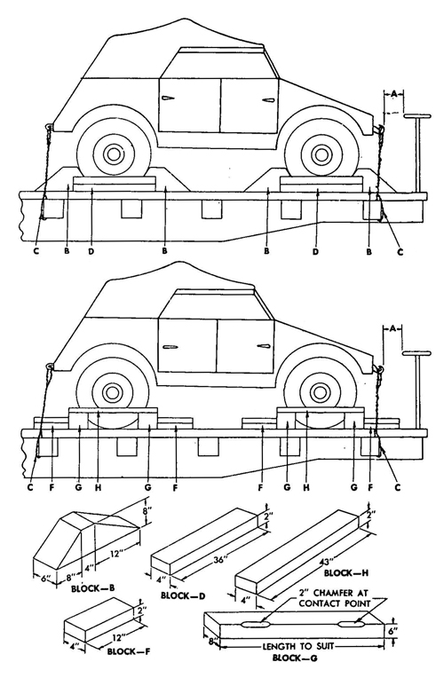
Figure 63 Blocking Requirements for Securing Vehicles on Railroad Cars
(2) METHOD 2 (fig. 63). Place four blocks "G", one to the front and one to the rear of each set of wheels. These blocks are to be at least 8 inches wider than the over-all width of the vehicle at the car floor. Using sixteen blocks "F", locate two against blocks "G" to the front of each wheel, and two against blocks "G" to the rear of each wheel. Nail the lower cleat to the floor with three 40-penny nails, and the top cleat to the cleat below with three 40-penny nails. Locate four cleats "H" on the outside of each wheel to the top of each block "G" with two 40-penny nails. Pass four strands, two wrappings, of No. 8 gage, black annealed wire "C", through tow hooks, front and rear, and through stake pockets on railroad car as described in Method 1 above.
d. Shipping data
| Shipping Data | Metric | US |
| Length, overall | 3,740 mm | 7 ft 10-1/2 in |
| Width, overall | 1,600 mm | 5 ft 5 in |
| Height, top down | 1,111 mm | 3 ft 8 in |
| Shopping weight | 725 kg | 1,598 lb |
| Approximate floor area | 6 sq m | 43 sq ft |
| Approximate volume | 7 cu m | 157 cu ft |
| Bearing pressure (lb per sg ft of floor area) | 37 | |
| Bearing pressure (kg per sq m of floor area) | 17 |